A highway height limit gantry and its height limit adjustment method

A high mast and height-limiting technology, which is applied in the field of highway height-limiting masts and height-limiting adjustments, can solve problems such as unsafe, cumbersome operations, and low precision, achieving high safety, ensuring lifting stability, The effect of saving labor costs

Active Publication Date: 2019-12-31
HEAVY EQUIP ENG CO LTD OF WUCHANG SHIPBUILDING IND
View PDF8 Cites 1 Cited by
  • Summary
  • Abstract
  • Description
  • Claims
  • Application Information

AI Technical Summary

Problems solved by technology

At present, there are many kinds of height-limited masts at various bridge intersections. The common permanent fixed height-limited masts cannot meet the needs of adjusting the height limit generated by complex road conditions.
The existing method is to use movable height-limiting components, and the two ends of the movable height-limiting components can be adjusted and fixed on the brackets at both ends. The defect is that the height of both ends of the main beam needs to be adjusted by manual measurement and operation, and the operation is cumbersome. Inefficient and less accurate
[0003] At the same time, the movable height-limiting components of some existing viaduct height-limiting masts use two chain hoists to respectively connect the ends of the movable height-limiting components. The lifting stability is good, but it is not very safe; if an operator is used to pull the chain block in turn, then the movable height limit component will shake to both sides, which is extremely unsafe; and after the movable height limit component reaches the specified height, the hand pull The hoist is always under stress, and the movable height limit component is always suspended on the chain hoist, which poses a safety hazard

Method used


Image

  • A highway height limit gantry and its height limit adjustment method
  • A highway height limit gantry and its height limit adjustment method
  • A highway height limit gantry and its height limit adjustment method

Examples


Embodiment 1

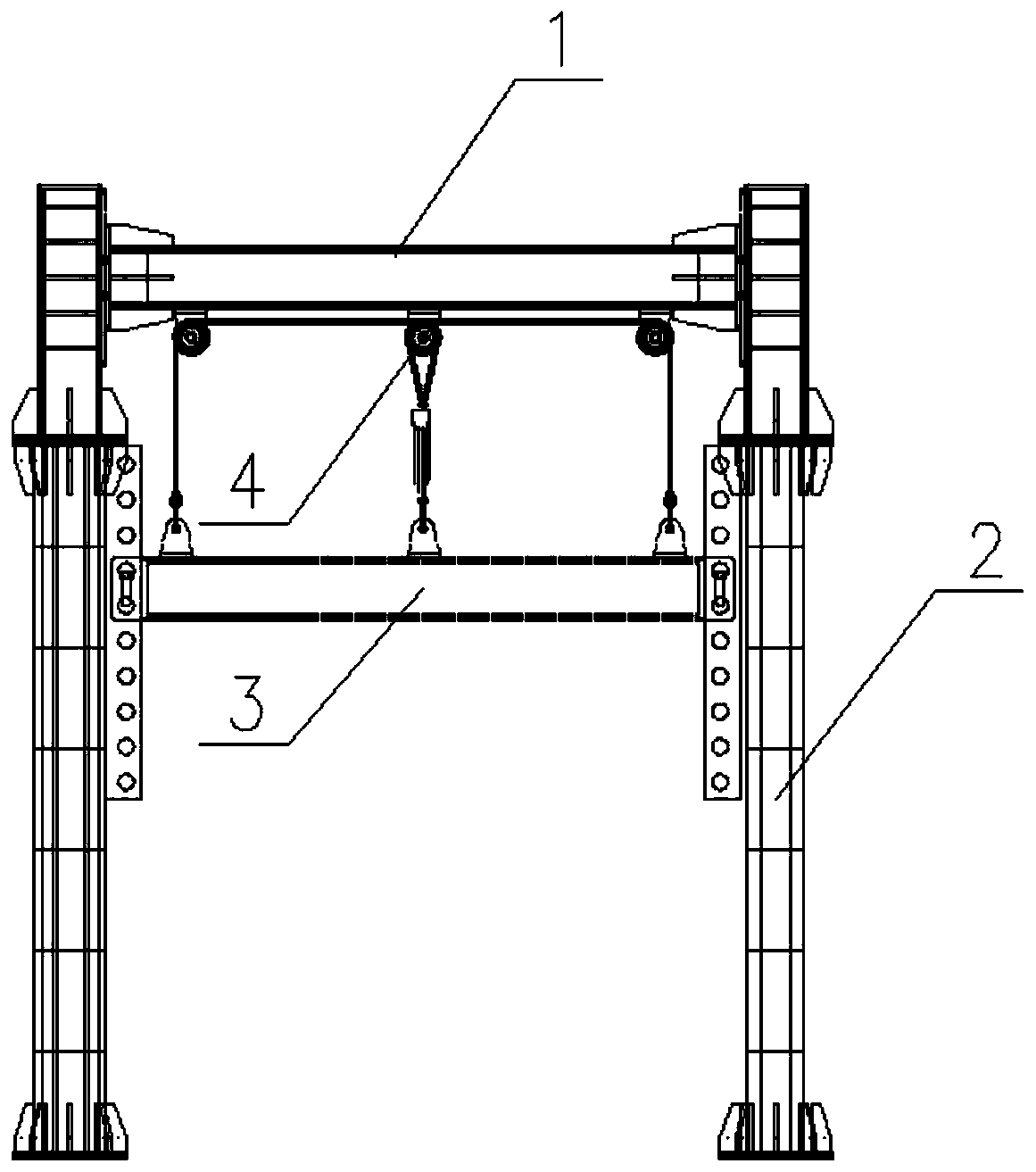
[0043] see figure 1 As shown, the embodiment of the present invention provides a highway height limit gantry, including:

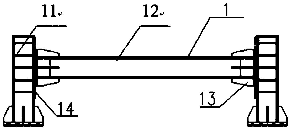
[0044] The upper main beam assembly 1 includes two vertical beams 11 and a cross beam 12 horizontally erected between the two vertical beams 11;

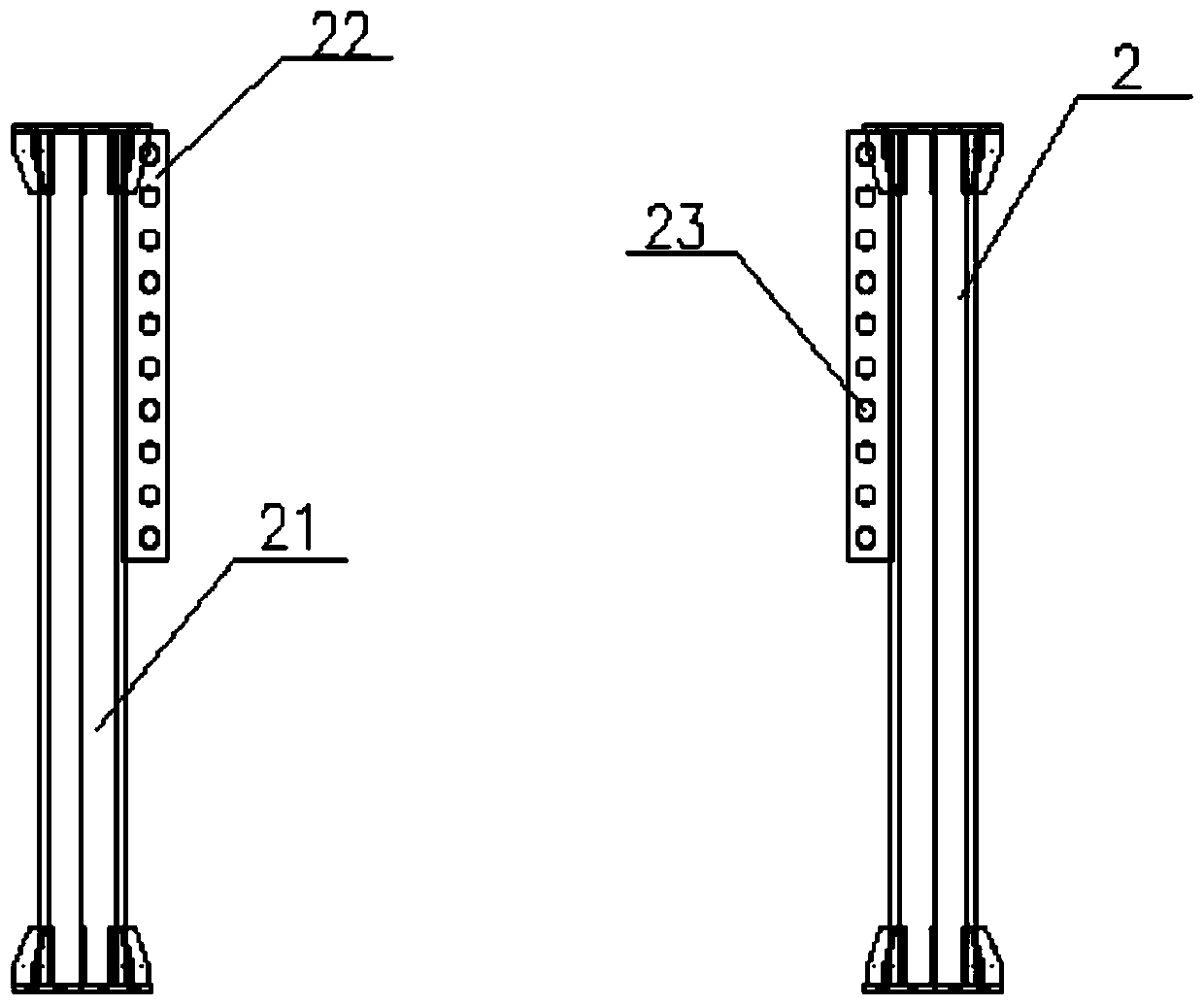
[0045] see image 3 As shown, the lower support assembly 2 includes two vertical beam support beams 21 and two hole-shaped height rulers 22. The two vertical beam support beams 21 are respectively arranged below the two vertical beams 11, and the two hole-shaped height rulers 22 are respectively It is fixed on the vertical beam support beam 21 along the height direction of the two vertical beam support beams 21; the hole-shaped height ruler 22 is provided with a plurality of vertically arranged round holes 23; the two hole-shaped height rulers 22 are fixed on the lower support assembly 2 On the same height, a plurality of circular holes 23 on the two hole-shaped height gauges 22 are located at the same height....

Embodiment 2

[0062] The embodiment of the present invention also discloses a height limit adjustment method for a highway height limit gantry:

[0063] The process of promoting the movable height limit assembly 3 includes:

[0064] Tighten the chain block 46 to make the lifting drive assembly 4 rise;

[0065] The two ends of the movable height limiting assembly 3 are fixed in the circular hole 23 of the hole-shaped height gauge 22;

[0066] Release the chain block 46 until the chain block 46 is not stressed.

[0067] The process of descending the movable height limit component 3 includes:

[0068] Pull the chain block 46 in reverse to make the lifting drive assembly 4 descend;

[0069] The two ends of the movable height limiting assembly 3 are fixed in the circular hole 23 of the hole-shaped height gauge 22;

[0070] Release the chain block 46 until the chain block 46 is not stressed.

Embodiment 3

[0072] The highway height limit gantry also includes two clamping shafts 5, and a clamping shaft fixing hole 31 is respectively provided at both ends of the movable height limiting assembly 3, and the clamping shaft 5 passes through one of the clamping shaft fixing holes 31 and the hole-shaped height gauge 22. Round hole 23. The height limit adjustment method of the highway height limit gantry is as follows:

[0073] 1. Adjust the height limit value, lift the movable height limit component 3 to the predetermined height, and allow higher motor vehicles to pass through.

[0074] First, slightly tighten the chain block 46, so that the lifting drive assembly 4 is in a stressed state; then continue to tighten the chain block 46, so that the movable height limit assembly 3 rises upward by 5 to 10 cm; then rotate the two clamping shafts 590 °Take out the card shaft 5; continue to tighten the chain block 46, so that the movable limit rod rises to the corresponding height hole on the ...


PUM


Abstract

The invention discloses a highway height-limiting door frame, and relates to the technical field of bridge and road equipment. The highway height-limiting door frame comprises an upper main beam assembly, which comprises two vertical beams and transverse beams installed between the two verticals beams; a lower supporting assembly, which comprises two vertical beams supporting beams and two strip hole-shaped height gauges, the two vertical beams supporting beams are installed under the two vertical beams respectively, and the two strip hole-shaped height gauges are fixed on the vertical beams supporting beams in the height direction of the two vertical beams supporting beams; a plurality of round holes which are vertically arranged are formed in the hole-shaped height gauges; a movable height-limiting assembly, which is horizontally installed under an upper main beam assembly, and the two ends of the movable height-limiting assembly are optionally installed in any round holes of the hole-shaped height gauges; a lifting driving assembly, which can drive the movable height-limiting assembly to ascend or descend. The highway height-limiting door frame has easy operation and can accurately adjust position limiting height. The invention further discloses a height-limiting adjustment method of the highway height-limiting door frame.

Description

technical field [0001] The invention relates to the technical field of bridge road equipment, in particular to a highway height-limiting gantry and a height-limiting adjustment method thereof. Background technique [0002] Along with the increase of various viaducts in the city, some crossings on the bridge need to limit the size of the vehicles on the bridge. At present, there are many kinds of height-limited masts at each upper bridge intersection, and the common permanent fixed height-limited masts cannot meet the needs of adjusting the height limit generated by complex road conditions. The existing method is to use movable height-limiting components, and the two ends of the movable height-limiting components can be adjusted and fixed on the brackets at both ends. The defect is that the height of both ends of the main beam needs to be adjusted by manual measurement and operation, and the operation is cumbersome. Low efficiency and low accuracy. [0003] At the same time...

Claims


Application Information

Patent Timeline
Patent Type & Authority Patents(China)
IPC IPC(8): E01F13/04
CPCE01F13/04E01F13/048
Inventor 程小龙陈世珍肖诗虎
Owner HEAVY EQUIP ENG CO LTD OF WUCHANG SHIPBUILDING IND
Why Eureka
Try Eureka