
Ventilation fan for degreasing

A ventilation fan and fan blade technology, applied in the field of ventilation fans, can solve problems that affect people's health, unclean cleaning, complicated operation, etc., and achieve the effects of saving manpower, increasing cleaning time, and increasing time for oil stains

Active Publication Date: 2019-04-26
宁波隆锐机械制造有限公司
View PDF6 Cites 0 Cited by
  • Summary
  • Abstract
  • Description
  • Claims
  • Application Information

AI Technical Summary

Problems solved by technology

Ventilation fans are often used on the doors and windows of household kitchens to discharge the cooking fumes outside the kitchen through the ventilation fans. However, if the ventilation fans are used for a long time, the oil stains produced in the kitchen will be attached to the ventilation fan blades. Generally, it is necessary to manually remove the ventilation fan. Use cleaning agent and water together to clean the oil stains on the blades of the ventilation fan, and then reinstall them on the doors and windows of the kitchen. Sometimes the cleaning is not clean, and it needs to be disassembled and cleaned repeatedly. It will affect the ventilation fan to discharge the indoor oil fume, causing the oil fume to stay in the kitchen for a long time, and people breathing oil fume for a long time will affect people's health

Method used


Image

  • Ventilation fan for degreasing
  • Ventilation fan for degreasing

Examples


Embodiment Construction

[0020] The following is further described in detail through specific implementation methods:

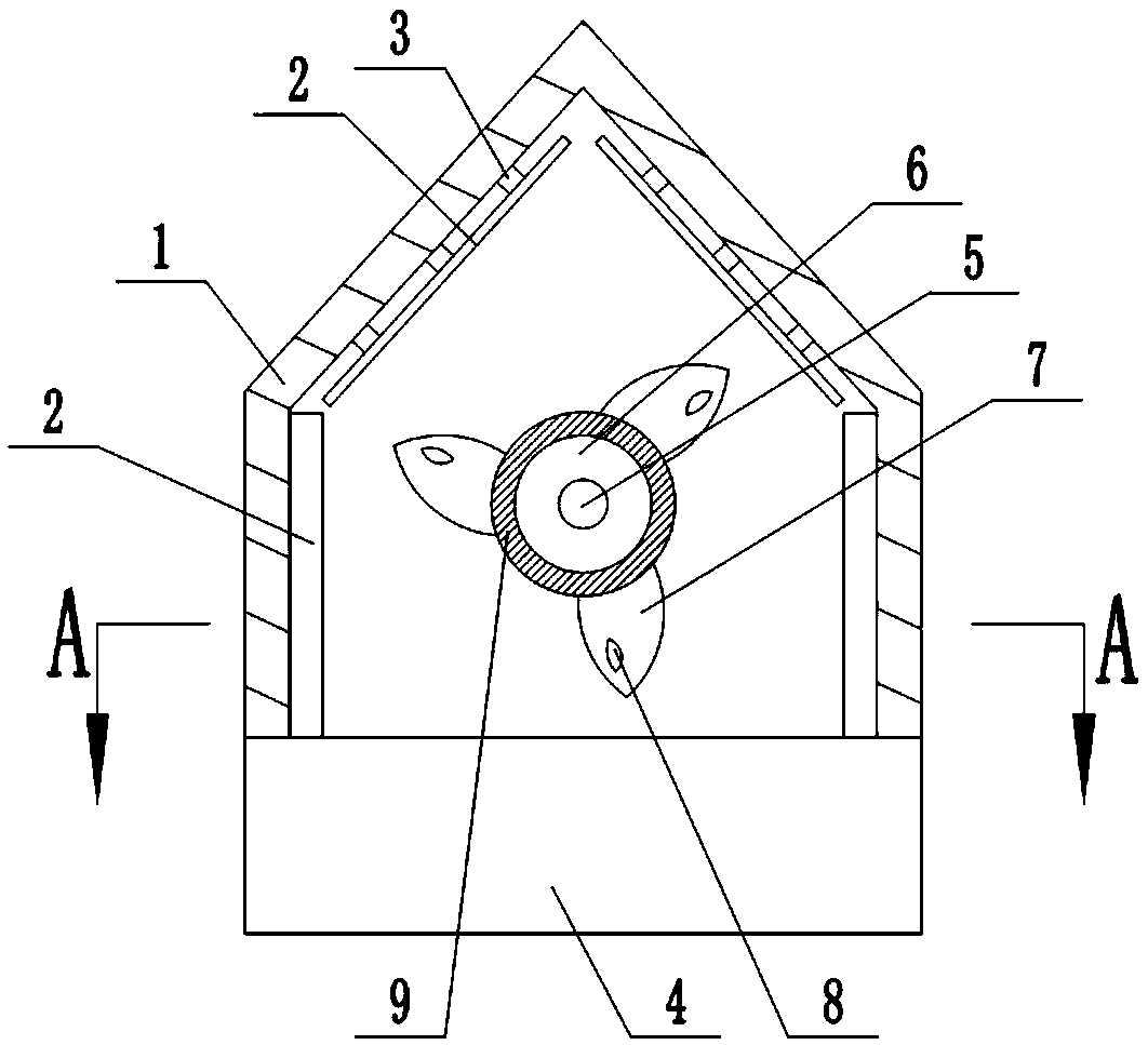
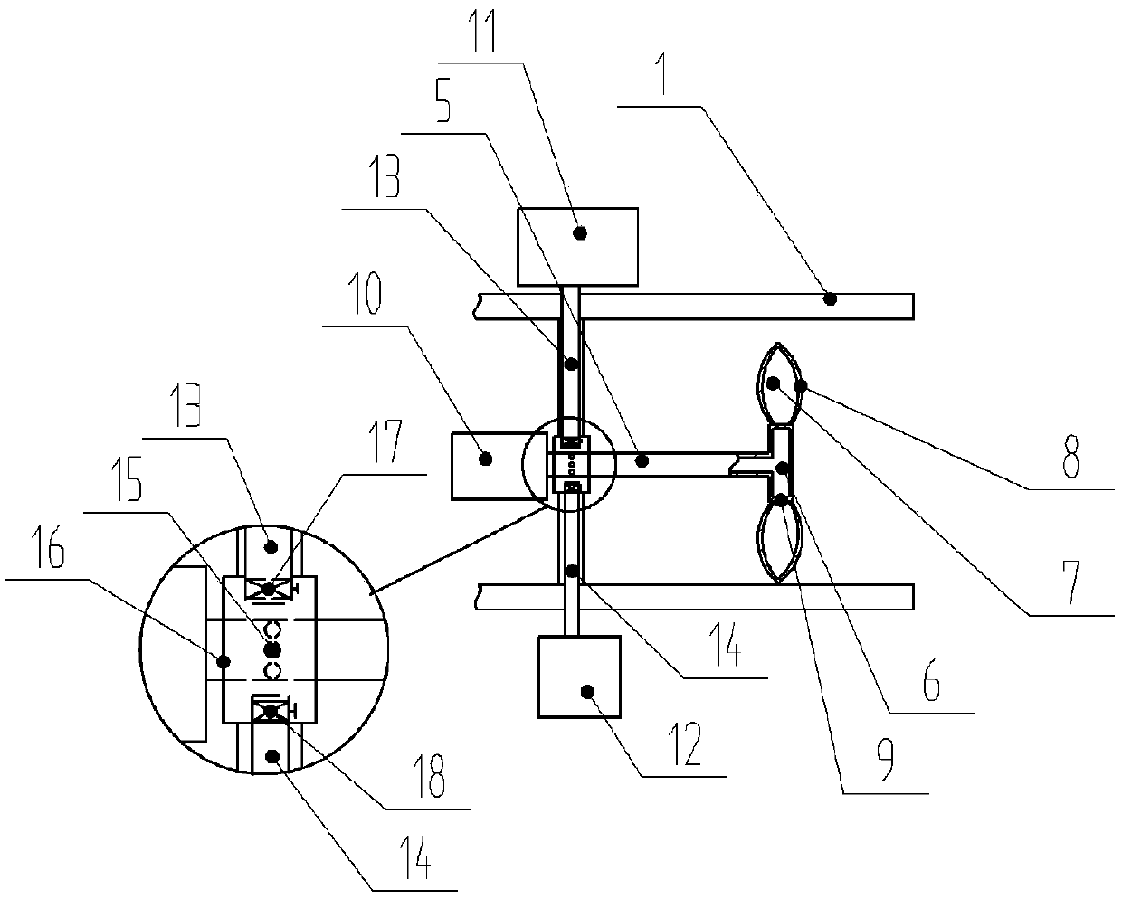
[0021] The reference signs in the drawings of the description include: housing 1, drainage plate 2, connecting column 3, collection tank 4, rotating shaft 5, flow tank 6, fan blade 7, oil inlet hole 8, water outlet hole 9, motor 10, the first A water tank 11, a second water tank 12, a first delivery pipe 13, a second delivery pipe 14, a water inlet 15, a fixed cover 16, a first valve 17, and a second valve 18.

[0022] Explanation: The up, down, left, and right sides or ends in the embodiments are subject to the up, down, left, and right sides or up, down, left, and right ends of the attached drawings.

[0023] The embodiment is basically as attached figure 1 Shown: the ventilation fan used to remove oil, including a prismatic shell 1, a prismatic through hole is opened in the center of the shell 1, drainage pipes are arranged on both sides of the shell 1, and a Six connecting colu...


PUM


Abstract

The invention discloses a ventilation fan for deoiling. The ventilation fan for deoiling comprises a prismatic shell; a prismatic through hole is formed in the center of the shell; a support rod is arranged between the inner walls of the shell, and is of a hollow structure; a motor is arranged on one side of the support rod; a running water box, positioned in the shell, is arranged on the other side of the support rod; a rotating shaft, penetrating through the middle part of the support rod, is arranged on an output shaft of the motor; the rotating shaft is of a hollow structure; a fixed coveris arranged in the connecting place of the rotating shaft and the support rod; a sealing ring is arranged on the peripheral side of the fixed cover; the rotating shaft is provided with multiple waterinlet holes positioned in the fixed cover; a conveying pipe is arranged in the support rod; and the conveying pipe penetrates through the fixed cover towards the water inlet holes. The ventilation fan for deoiling further comprises a water tank; the conveying pipe is connected with the water tank; the rotating shaft extends out of the support rod to communicate with the running water box; multiple fan blades are arranged on the running water box; the fan blades are of hollow structures, and are provided with oil inlet holes; and water outlet holes are formed in the connecting places of the fan blades and the running water box. When oil stain is absorbed, the service life of the fan blades is prolonged; and frequent cleaning of the fan blades is not needed.

Description

technical field [0001] The invention belongs to the technical field of household appliances, in particular to a ventilating fan used for degreasing. Background technique [0002] The ventilating fan is installed on the partition wall hole, and is used for exchanging air from one side of the partition wall to the other. It can adjust indoor air and remove indoor smoke and dust. Ventilation fans are often used on the doors and windows of household kitchens to discharge the cooking fumes outside the kitchen through the ventilation fans. However, if the ventilation fans are used for a long time, the oil stains produced in the kitchen will be attached to the ventilation fan blades. Generally, it is necessary to manually remove the ventilation fan. Use cleaning agent and water together to clean the oil stains on the blades of the ventilation fan, and then reinstall them on the doors and windows of the kitchen. Sometimes the cleaning is not clean, and it needs to be disassembled a...

Claims


Application Information

Patent Timeline
Patent Type & Authority Patents(China)
IPC IPC(8): F04D25/06F04D29/70
CPCF04D25/0606F04D29/703
Inventor 王健
Owner 宁波隆锐机械制造有限公司
Learn More