Damping brake device

A brake device and damping technology, which is applied in the direction of brake type, axial brake, brake parts, etc., can solve the problem of poor braking efficiency and heat dissipation of drum brakes, poor braking damping stability, small braking friction area, etc. problems, to achieve the effect of reducing impact, increasing brake damping force, and reducing impact noise

Active Publication Date: 2018-05-04
HEBEI HANGUANG HEAVY IND
View PDF4 Cites 4 Cited by
  • Summary
  • Abstract
  • Description
  • Claims
  • Application Information

AI Technical Summary

Problems solved by technology

[0003] For example, the brake friction area of ​​the disc brake device is small, and the brake hydraulic pressure required is high, and the brake device with a hydraulic device can only be used; the brake pad and the brake disc are installed independently, and the relationship between the two needs to be adjusted after installation. The relative position between them makes the brake clearance and other parameters meet the braking requirements; when the rotating part rotates in both forward and reverse directions, the drum-type single brake pad can only maintain a large braking force in the reverse direction for braking damping, while the opposite direction The braking force is very small, and the braking damping effect is very weak; and in the disc brake, the disc surface is easy to warp and uneven when the brake disc is used, and the braking damping stability is poor when the brake disc brakes
[0004] The braking efficiency and heat dissipation of drum brakes are poor, and a large amount of heat will be accumulated during the braking process. The brake should be regularly adjusted to the clearance of the brake shoe

Method used


Image

  • Damping brake device
  • Damping brake device
  • Damping brake device

Examples


Embodiment Construction

[0026] The present invention will be further described in detail below in conjunction with the accompanying drawings and embodiments.

[0027] This embodiment provides a damping braking device. In the damping braking device, the relative position of the rotating part and the damping part is fixed, and the installation is convenient; and when the rotating part rotates positively and negatively, it can play the role of braking and damping, and the braking in both directions The damping effect is the same.

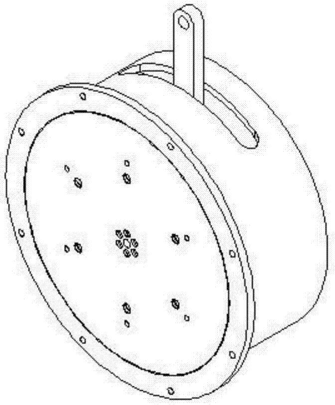
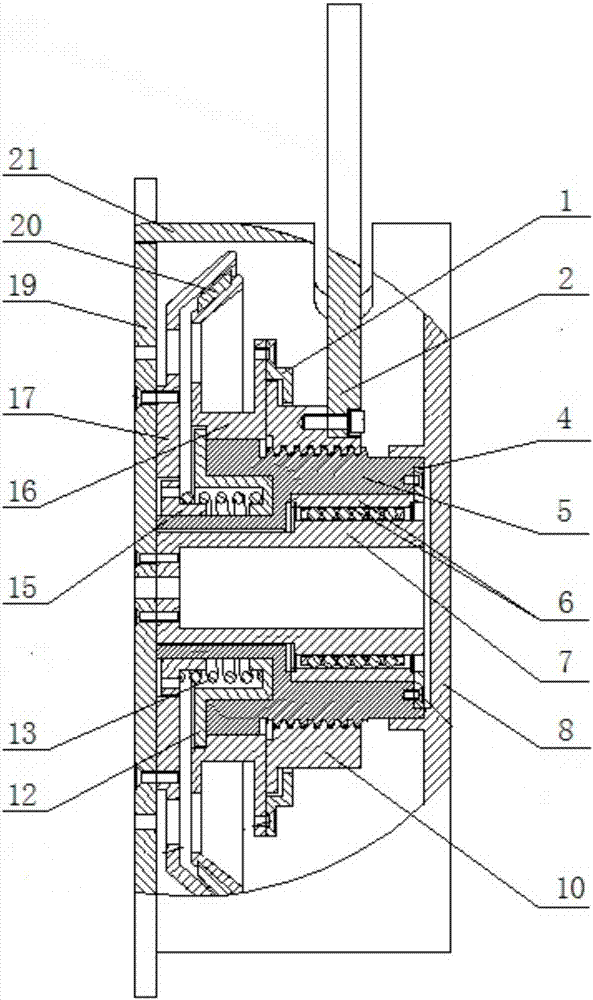
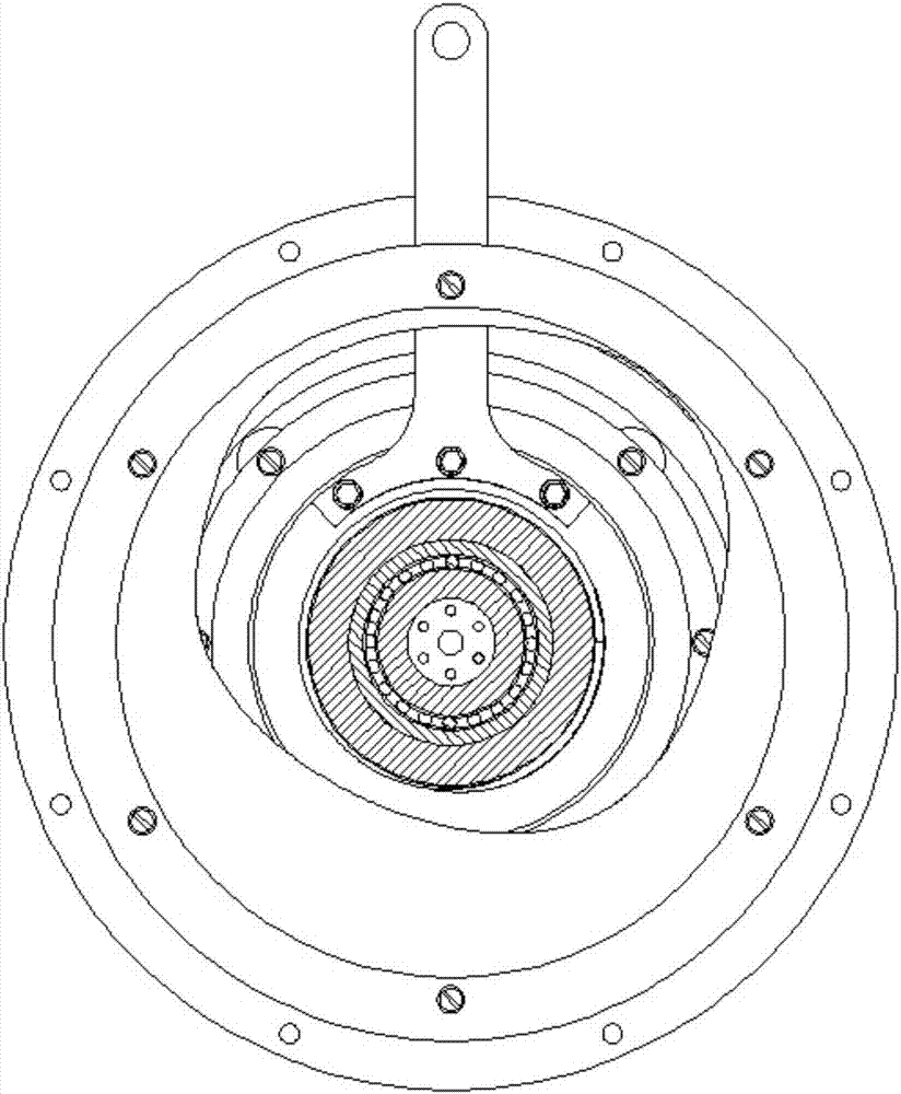
[0028] like Figure 1-3 As shown, the damping braking device includes: a rotating member, a damping member, a friction member, a connecting member and a braking force applying member.

[0029] Among them, the rotating part includes: left mounting plate 19, stop disc 17 and connecting shaft 7; the damping part includes: damping disc 16 and compression cylinder 10; The right mounting plate 8 and the housing 21; the braking force applying member includes: the separator 1 and t...


PUM


Abstract

The invention provides a damping brake device. According to the damping brake device, a braking force applying part and a stopping part are combined into a whole, so that the relative position of thebraking force applying part and the stopping part is fixed, the gap value of each part is adjusted in advance, no secondary adjustment is needed during installation, and therefore the installation isconvenient; the braking force applying part and the stopping part are oppositely moved in the axial direction, and automatic centre align is achieved through self-conical structure, so that the stability is good during braking damping; a compression part of the braking force applying part is in spiral axial movement, the movement precision is high, threads of the compression part are self-lockingthreads, so that braking damping force is guaranteed to be applied smoothly, the braking damping force is not automatically reduced, and the device is stable and reliable; a return spring aids the braking force applying part to return to an original position, the brake damping force is relieved, and moving of a mechanism is stable and noiseless; and the device is not influenced by positive and negative rotation directions of rotating parts, the braking damping effect can be achieved in the positive and negative directions, and the braking damping effect is the same.

Description

technical field [0001] The invention relates to a damping and braking device, in particular to a damping and braking device for rotating parts, which is especially suitable for rotating parts with high requirements on braking damping, safety and reliability, and belongs to the field of machinery. Background technique [0002] Damping braking devices have been widely used in many fields of military and civilian use. At present, most of the terminal braking actuators of pneumatic, hydraulic and electromagnetic damping deceleration devices that are widely used are drum or disc damping brake devices, but they have some shortcomings. [0003] For example, the brake friction area of ​​the disc brake device is small, and the brake hydraulic pressure required is high, and the brake device with a hydraulic device can only be used; the brake pad and the brake disc are installed independently, and the relationship between the two needs to be adjusted after installation. The relative p...

Claims


Application Information

Patent Timeline
Patent Type & Authority Applications(China)
IPC IPC(8): F16D55/14F16D65/097
Inventor 邵长春杜振华曲展刘海涛杨夫云
Owner HEBEI HANGUANG HEAVY IND
Why Eureka
Try Eureka