Shaking head camera capable of rotating 360 degrees

A camera, the technology of the other side, applied in the field of moving head camera, can solve the problems of remote control angle limitation, lack of feedback, high cost of a single device, and achieve the effect of not easy to fall off and stable structure

Pending Publication Date: 2018-05-04
深圳市海雀科技有限公司
View PDF7 Cites 3 Cited by
  • Summary
  • Abstract
  • Description
  • Claims
  • Application Information

AI Technical Summary

Problems solved by technology

[0003] 1. The remote control angle is limited. figure 1 It shows a universal remote control device in the prior art. This universal remote control device has more than 6 multi-directional infrared emitting tubes built in it in order to achieve omnidirectional remote control requirements, but it is still not perfect. To meet the three-dimensional 360° full coverage requirements;
[0004] 2. Lack of feedback during remote control. Infrared remote control is one-way control, and the control results cannot be fed back to the control end immediately. After the control operation is completed, the controller does not know whether the control is really effective;
[0005] 3. The cost of a single device is too high. The sales price of a single universal remote control product on the market is around 100 yuan, and it only has a monitoring function.

Method used


Image

  • Shaking head camera capable of rotating 360 degrees

Examples


Embodiment

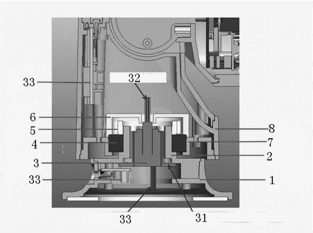
[0023] like figure 1 As shown, the present invention is a 360-degree rotating head camera. A 360-degree rotating head camera includes a rotating bottom case 2 on the upper end of the base case 1, a bearing 4 on one side of the rotating bottom case 2, and a bearing 4 on the other side. A slip ring 3 is arranged on the side, and a movable gear 5 is arranged on the upper surface of the slip ring 3, and the outer side of the movable gear 5 is protected by a motor bracket 6. A through hole is arranged in the middle of the rotating bottom case 2, and the slip ring 3 is arranged in the through hole. Power is supplied through wires and PCBA power board. The rotation angle of the traditional moving head camera is 0 to 360 degrees reciprocating operation; the main reason is that it is limited by the connection line between the head and the body. When the head rotates, the connection line will be twisted and subject to a certain twisting force. The larger the rotation angle The greater ...


PUM


Abstract

The invention discloses a shaking head camera capable of rotating 360 degrees. A rotating bottom shell is arranged on an upper end of a base shell, a bearing is arranged on one side of the rotating bottom shell, a sliding ring is arranged on the other side of the rotating bottom shell, a movable gear is arranged on an upper end face of the sliding ring, the outer side of the movable gear is protected by a motor bracket, a through hole is formed in the middle of the rotating bottom shell, and the sliding ring is arranged in the through hole and is powered by a conducting wire and a PCBA power supply small board. The rotating angle of the traditional shaking head camera is 0-360 degrees, which mainly results from the fact that due to the limitation of a connecting line of a head and a machine body, the connecting line is twisted with the head rotated and is applied with a certain torsion, the torsion born by the wire is greater when the rotating angle is larger, therefore the traditionalconnection mode is difficult to achieve large-angle rotation; the new shaking head camera rotating mechanism adopts the sliding ring, which is similar to an electric brush of a motor; the connectingline of the head and the machine body is replaced by the sliding ring; and the internal structure of the sliding ring is in contact connection with an elastic sheet, and thus is not limited from running within 360 degrees.

Description

technical field [0001] The invention relates to a moving head camera, in particular to a moving head camera capable of rotating 360 degrees. Background technique [0002] There are currently two mature forms of products, one is a home-use movable head camera, and the other is a home-use universal remote control device. There are several obvious usage defects: [0003] 1. The remote control angle is limited. figure 1 It shows a universal remote control device in the prior art. This universal remote control device has more than 6 multi-directional infrared emitting tubes built in it in order to achieve omnidirectional remote control requirements, but it is still not perfect. To meet the three-dimensional 360° full coverage requirements; [0004] 2. Lack of feedback during remote control. Infrared remote control is one-way control, and the control results cannot be fed back to the control end immediately. After the control operation is completed, the controller does not know...

Claims


Application Information

Patent Timeline
Patent Type & Authority Applications(China)
IPC IPC(8): H04N5/225H01R35/00
CPCH01R35/00H04N23/00
Inventor 王森易州刘建飞
Owner 深圳市海雀科技有限公司
Why Eureka
Try Eureka