Firefighting water supplying and fire extinguishing equipment monitoring system

A technology of fire extinguishing equipment and monitoring system, which is applied in the field of fire fighting equipment, can solve problems such as backward detection methods, high labor intensity, and harsh working environment, and achieve the effects of smooth and easy to use water flow, improved work efficiency, and convenient inspection and maintenance

Pending Publication Date: 2018-05-08
尹小东
View PDF7 Cites 4 Cited by
  • Summary
  • Abstract
  • Description
  • Claims
  • Application Information

AI Technical Summary

Problems solved by technology

[0002] In the fire water system, normalized detection and control are required, such as the pressure and flow monitoring of the tap water pipe network. The necessity of monitoring it is that it can be replenished in time when the water level of the fire pool and water tank is insufficient; Monitor whether the fire-fighting water volume meets the requirements of fire-fighting water volume; monitor the fire-fighting pump room, monitor the outlet pressure of various fire-fighting pumps; monitor the water volume and temperature of the fire-fighting external network entry terminal, trench pipeline, local pipeline, fire well valve, trench pipe network Frost damage or blockage of other parts will cause insufficient water pressure and water source of fire extinguishing equipment, which will affect the normal use of the equipment and cause irreversible consequences
At present, all inspections are performed manually by special personnel, with backward inspection methods, high labor intensity and harsh working environment.

Method used


Image

  • Firefighting water supplying and fire extinguishing equipment monitoring system
  • Firefighting water supplying and fire extinguishing equipment monitoring system
  • Firefighting water supplying and fire extinguishing equipment monitoring system

Examples


Embodiment Construction

[0031] The present invention will be further described below in conjunction with accompanying drawing:

[0032] As shown in the figure, U is an integrated circuit, C is a capacitor, R is a resistor, and L is an inductance coil.

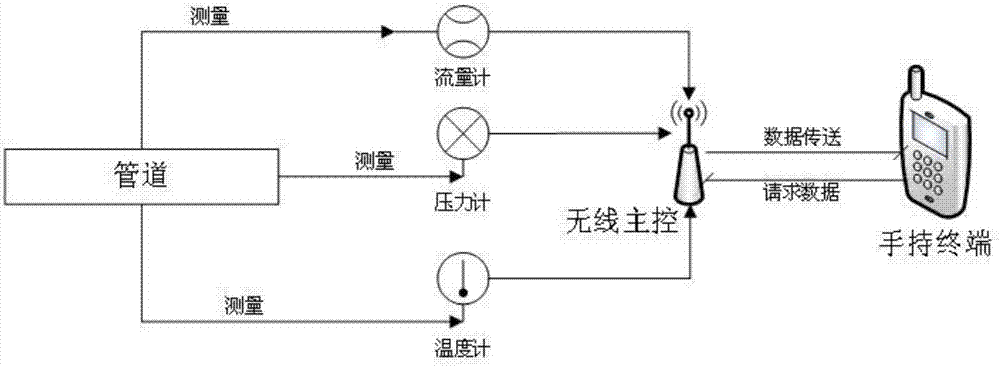
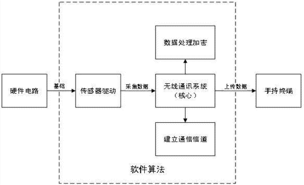
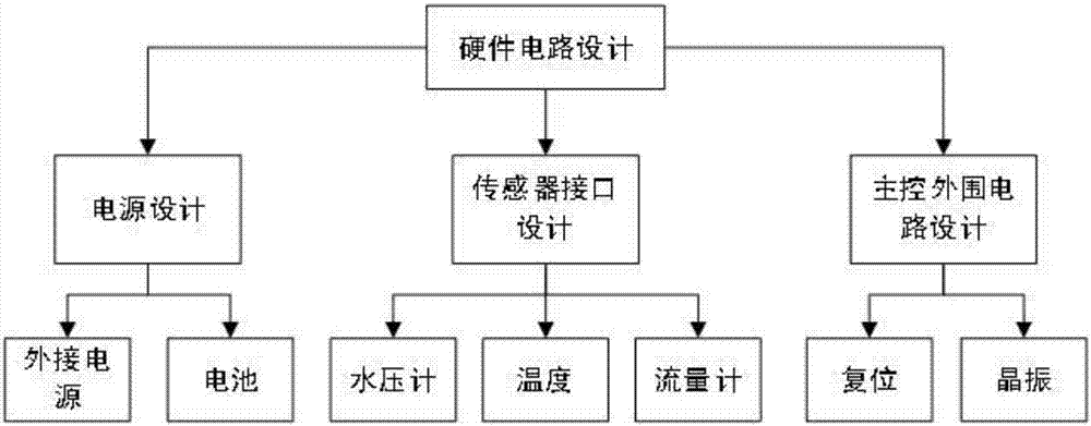
[0033] The invention consists of hardware circuit design, sensor drive design, wireless communication system design, and software algorithm design. Among them, the hardware circuit design connects each hardware unit into a whole, so that each unit can work together, which is the basis for the stable and reliable operation of the whole system. The sensor driver design is the basis for each sensor to work normally. The wireless communication system interacts with the sensor through the driver of each sensor, and can quickly and accurately obtain the value of each sensor. The design of the wireless communication system is the core of the whole system. Its main functions are, on the one hand, to obtain the value of the sensor, and on the other hand, to e...


PUM


Abstract

The invention discloses a firefighting water supplying and fire extinguishing equipment monitoring system, and belongs to the technical field of firefighting equipment. The firefighting water supplying and fire extinguishing equipment monitoring system is characterized in that a water pressure meter, a flow meter and a temperature sensor are connected with the input end of a drive circuit of a sensor through a sensor connector, the output end of the drive circuit is connected with the input end of a master controller, and a wireless communication unit and a wireless handheld terminal are in frequency-to-frequency echoing. The firefighting water supplying and fire extinguishing equipment monitoring system has the beneficial effects that firstly, home-entry end firefighting water source monitoring is conducted, for example, pressure and flow of a tap water pipe net and the like are monitored, and according to the necessity of home-entry end firefighting water source monitoring, when thewater level of a firefighting water pond and a water tank is insufficient, timely supplementing can be conducted; secondly, firefighting water pond and water tank water level monitoring is achieved; thirdly, firefighting pump room monitoring is conducted; and fourthly, water volume and temperature monitoring of a firefighting outer net home-entry end, a trench pipeline and a local pipeline is conducted.

Description

technical field [0001] The invention belongs to the technical field of fire fighting equipment. Background technique [0002] In the fire water system, normalized detection and control are required, such as the pressure and flow monitoring of the tap water pipe network. The necessity of monitoring it is that it can be replenished in time when the water level of the fire pool and water tank is insufficient; Monitor whether the fire-fighting water volume meets the requirements of fire-fighting water volume; monitor the fire-fighting pump room, monitor the outlet pressure of various fire-fighting pumps; monitor the water volume and temperature of the fire-fighting external network entry terminal, trench pipeline, local pipeline, fire well valve, trench pipe network Frost damage or freezing blockage of other parts will cause insufficient water pressure and water source of fire extinguishing equipment, which will affect the normal use of the equipment and cause irreversible conse...

Claims


Application Information

Patent Timeline
IPC IPC(8): A62C37/50
CPCA62C37/50
Inventor 尹小东
Owner 尹小东
Why Eureka
Try Eureka