
Punching machine

A stamping machine and pressing module technology, applied in the stamping and forming field of steel pipes, can solve the problems of low forming efficiency, difficulty in popularization and use, unqualified special-shaped steel parts, etc., and achieve the effect of improving forming efficiency, facilitating popularization and use, and improving position accuracy

Pending Publication Date: 2018-05-08
重庆鹏林钢结构有限责任公司
View PDF7 Cites 4 Cited by
  • Summary
  • Abstract
  • Description
  • Claims
  • Application Information

AI Technical Summary

Problems solved by technology

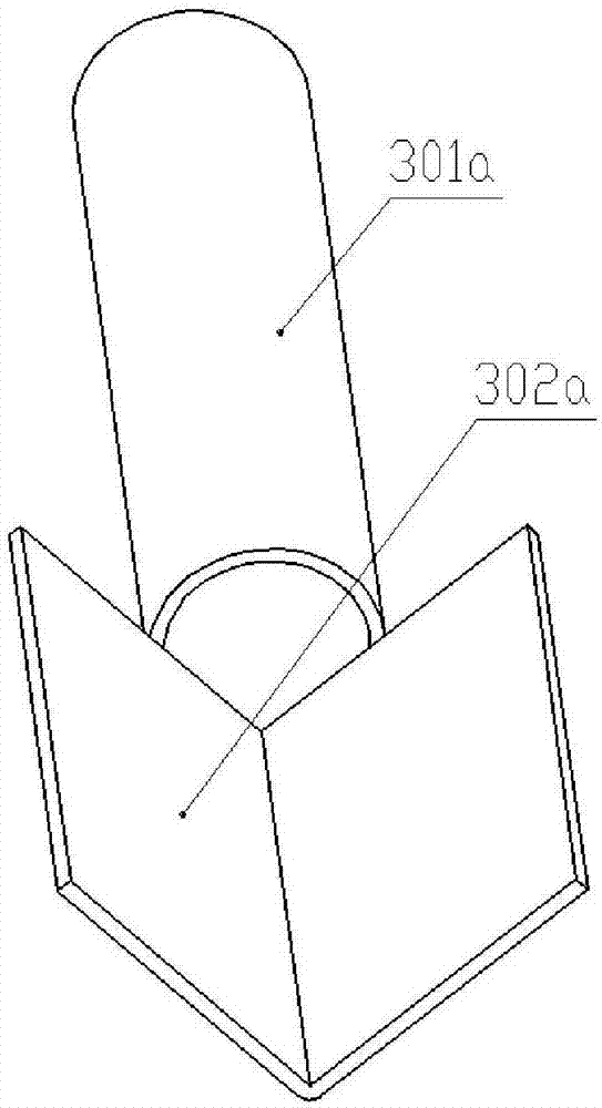
[0002] Steel pipes are widely used as structural parts in various steel structure projects. There is a special-shaped steel part such as figure 1 As shown, it consists of a round pipe section 301a and an angle steel section 302a. In the existing manufacturing, the round pipe section 301a and the angle steel section 302a are usually processed separately first, and then welded and fixed as one. The position accuracy between the pipe section 301a and the angle steel section 302a is too serious, and due to economic cost considerations, the round pipe section 301a and the angle steel section 302a usually cannot obtain reliable quality, thus causing the above-mentioned special-shaped steel parts to be unqualified. The reason is that there are many ways to manufacture steel pipes at present, such as casting, turning and forming, etc., but most of them have low forming efficiency. For cold-rolled steel pipes, the existing cold-rolling process and equipment quality are uneven, and the forming is fast. The equipment with good forming quality is often expensive and complex in structure, which is difficult to popularize and use, which limits the improvement of the forming quality of the round pipe section 301a. Due to the specificity of the structure, the bending equipment mostly stamps and forms steel instantly. The quality of the forming is poor, and the processing is relatively rough. Manually assisted demoulding is required to separate the workpiece. The efficiency is slightly low, and it can only be used for "angle steel" products with a single angle. Stamping and bending is not efficient, has poor versatility, and is inconvenient to manage, so it also greatly limits the batch high-quality forming process of the angle steel section 302a

Method used


Image

  • Punching machine
  • Punching machine
  • Punching machine

Examples


Embodiment Construction

[0035] The implementation of the present invention will be illustrated by specific specific examples below, and those skilled in the art can easily understand other advantages and effects of the present invention from the contents disclosed in this specification.

[0036] Below in conjunction with accompanying drawing and embodiment the present invention will be further described:

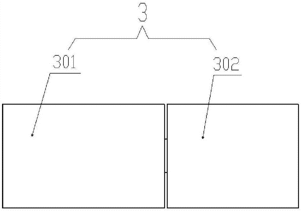
[0037] A stamping machine, including a steel pipe rolling device and a steel plate bending mechanism arranged side by side, wherein the steel pipe rolling device is used to make the steel pipe part, and the steel plate bending mechanism is used to make the angle steel part, so it is necessary to prepare in advance such as figure 2 In the plate blank shown, the first plate 301 is correspondingly stamped into a round pipe section 301a, and the second plate 302 is correspondingly stamped into an angle steel section 302a. In order to clearly show the structure of the steel pipe rolling device and the st...


PUM


Abstract

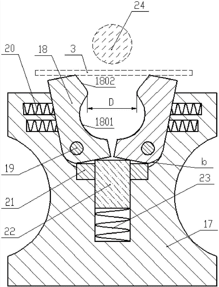
The invention discloses a punching machine. The punching machine comprises a steel pipe rolling device and a steel plate bending mechanism which are arranged side by side. A step groove is formed in the middle of a base of the steel pipe rolling device and comprises a first groove, a second groove and a third groove. The lower left corner of a left press module and the lower right corner of a right press module are hinged to the side walls of the first groove correspondingly. The groove bottom of the third groove is fixedly connected with the bottom end of a second spring, and the top end of the second spring is connected with an ejector rod. A blind hole is vertically formed in the middle of a base plate of the steel plate bending mechanism, a spring is arranged at the bottom of the blindhole, and the bottom end of the spring is fixed to the hole bottom of the blind hole. Supports are arranged on the two sides of the ejector rod correspondingly. Each support comprises a right-angle block and a back plate in a flat plate shape. A mold plate is hinged in each right-angle opening, one end of each mold plate is hinged to the corresponding back plate, each hinged shaft is perpendicular to the corresponding back plate, and two chamfers on the edge of the upper surface of the other end of each mold plate are jointed into a V-shaped mold cavity. The punching machine is high in forming efficiency, good in forming quality, simple and ingenious in structure and beneficial to use and popularization.

Description

technical field [0001] The invention belongs to the technical field of steel processing, and in particular relates to stamping forming of steel pipes. Background technique [0002] Steel pipes are widely used as structural parts in various steel structure projects. There is a special-shaped steel part such as figure 1 As shown, it consists of a round pipe section 301a and an angle steel section 302a. In the existing manufacturing, the round pipe section 301a and the angle steel section 302a are usually processed separately first, and then welded and fixed as one. The position accuracy between the pipe section 301a and the angle steel section 302a is too serious, and due to economic cost considerations, the round pipe section 301a and the angle steel section 302a usually cannot obtain reliable quality, thus causing the above-mentioned special-shaped steel parts to be unqualified. The reason is that there are many ways to manufacture steel pipes at present, such as casting, t...

Claims


Application Information

Patent Timeline
IPC IPC(8): B21D37/10B21D45/04B21D5/06B21D5/10
CPCB21D5/06B21D5/10B21D37/10B21D45/04Y02P70/10
Inventor 邹玲邹开贵李俊杰尹贵波邹开禄李小军郭维君
Owner 重庆鹏林钢结构有限责任公司
Learn More