
Sheet torsion rod spring structure, vehicle suspension and manufacturing method of sheet torsion rod spring structure

A manufacturing method and a torsion bar spring technology, which are applied in the manufacture of sheet torsion bar spring structures and in the field of vehicle suspension, can solve the problems of heavy weight, large change angle of the transmission shaft, and large change in the angle of the transmission shaft, so as to achieve production and replacement. Low cost, small change in drive shaft angle, and the effect of improving smooth performance

Inactive Publication Date: 2018-05-08
株洲春华实业有限责任公司
View PDF5 Cites 2 Cited by
  • Summary
  • Abstract
  • Description
  • Claims
  • Application Information

AI Technical Summary

Problems solved by technology

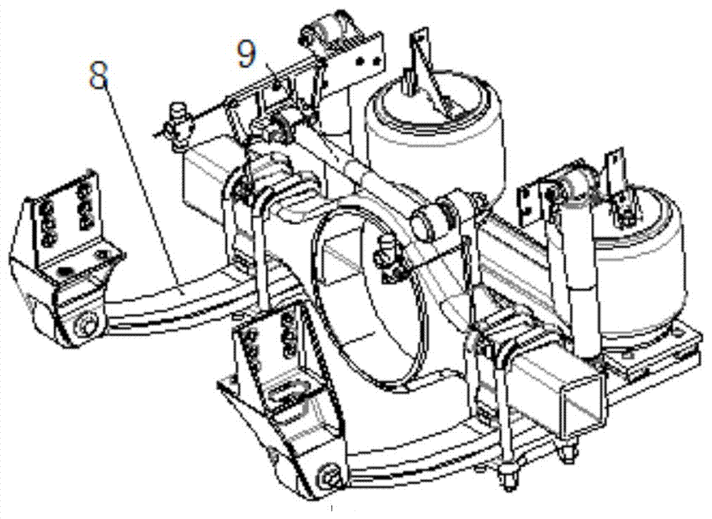
[0002] The traditional truck air suspension structure such as image 3 and Figure 4 as shown, image 3 The suspension guide mechanism is composed of the lower two guide arm assemblies 8 and the upper transverse thrust rod 9. When the axle jumps, it rotates around the center of the guide arm roll lug, and the angle of the transmission shaft changes greatly, especially for 6x4 double drive axles; Figure 4 The suspension guiding mechanism is composed of the lower two longitudinal thrust rods 10 and the upper V-shaped thrust rod, and the lateral stabilizer rod 11 plays an anti-rolling role. The air suspension has complex structure and heavy weight, and the angle of the transmission shaft changes greatly during transmission. Large, which in turn affects the ride comfort of the vehicle, leading to problems such as poor ride comfort

Method used


Image

  • Sheet torsion rod spring structure, vehicle suspension and manufacturing method of sheet torsion rod spring structure
  • Sheet torsion rod spring structure, vehicle suspension and manufacturing method of sheet torsion rod spring structure
  • Sheet torsion rod spring structure, vehicle suspension and manufacturing method of sheet torsion rod spring structure

Examples


Embodiment Construction

[0027] The embodiments of the present invention will be described in detail below with reference to the accompanying drawings, but the present invention can be implemented in many different ways defined and covered by the claims.

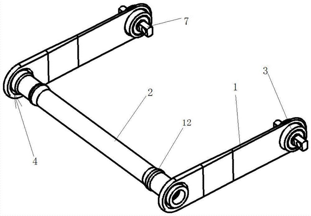
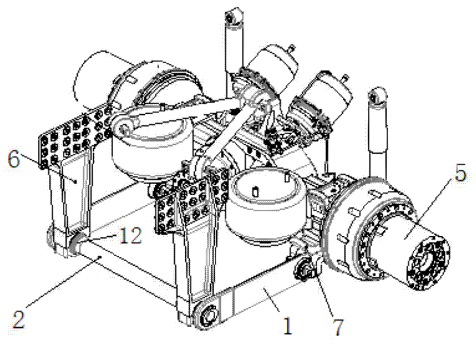
[0028] Such as Figure 1-Figure 2 As shown, the embodiment of the present invention first discloses a leaf torsion bar spring structure, including two leaf springs 1 and a torsion bar 2, one end of any one leaf spring 1 is welded to one end of the torsion bar 2, and the other One end is fixedly connected with a spherical hinge bushing 3, and the two spherical hinge bushings 3 are coaxial and their centerlines are parallel to the centerline of the torsion bar 2 to form a similar parallelogram structure.

[0029] In this embodiment, in order to further reduce weight and realize lightweight design, after finite element simulation analysis, the stress of leaf spring 1 decreases from the connection with torsion bar 2 to the direction of ball joint bushin...


PUM


Abstract

The invention discloses a sheet torsion rod spring structure, vehicle suspension and a manufacturing method of the sheet torsion rod spring structure. The torsion rod spring structure comprises two sheet type plate springs and a torsion rod, one end of either of the two sheet type plate springs is fixedly connected with one end of the torsion rod, the other end of either of the two sheet type plate springs is fixedly connected with a spherical hinge lining, the two spherical hinge linings are coaxial, and the central lines of the two spherical hinge linings are parallel with the central line of the torsion rod. The suspension makes up-down translational motion when a vehicle axle jumps, the angular change of a transmission shaft is small, and thus the smooth-going property of a vehicle isimproved. Meanwhile, because a transverse stabilizing rod and a lower longitudinal thrust rod are manufactured into a whole , the sheet torsion rod spring air suspension is simpler and more compact instructure, the suspension is low in weight, and the production cost is low.

Description

technical field [0001] The invention relates to the field of vehicle suspension, in particular to a leaf torsion bar spring structure, a vehicle suspension using the leaf torsion bar spring structure and a manufacturing method of the leaf torsion bar spring structure. Background technique [0002] The traditional truck air suspension structure such as image 3 and Figure 4 as shown, image 3 The suspension guide mechanism is composed of the lower two guide arm assemblies 8 and the upper transverse thrust rod 9. When the axle jumps, it rotates around the center of the guide arm roll lug, and the angle of the transmission shaft changes greatly, especially for 6x4 double drive axles; Figure 4 The suspension guiding mechanism is composed of the lower two longitudinal thrust rods 10 and the upper V-shaped thrust rod, and the lateral stabilizer rod 11 plays an anti-rolling role. The air suspension has complex structure and heavy weight, and the angle of the transmission shaft ch...

Claims


Application Information

Patent Timeline
Patent Type & Authority Applications(China)
IPC IPC(8): B60G11/44B23P15/00
CPCB23P15/00B60G11/44
Inventor 何建成李海波李勇锋
Owner 株洲春华实业有限责任公司
Learn More