Automatic lubricating device for guide rail

An automatic lubrication, guide rail technology, applied in the direction of engine lubrication, lubricating oil container, lubricating parts, etc., can solve the problems of waste, unable to add all the lubricating grease, and the amount of lubricating grease cannot be controlled, and achieve the effect of reducing waste.

Inactive Publication Date: 2018-05-08
JINHUA JINGYING TECH SERVICE CO LTD
View PDF0 Cites 4 Cited by
  • Summary
  • Abstract
  • Description
  • Claims
  • Application Information

AI Technical Summary

Problems solved by technology

[0004] The purpose of the present invention is to solve the problem in the prior art that lubricating grease cannot be fully added between the guide rail and the slider, and the amount of added lubricating grease cannot be controlled and will cause

Method used


Image

  • Automatic lubricating device for guide rail
  • Automatic lubricating device for guide rail

Examples


Embodiment Construction

[0019] The technical solutions of the present invention will be further specifically described below through specific embodiments and in conjunction with the accompanying drawings.

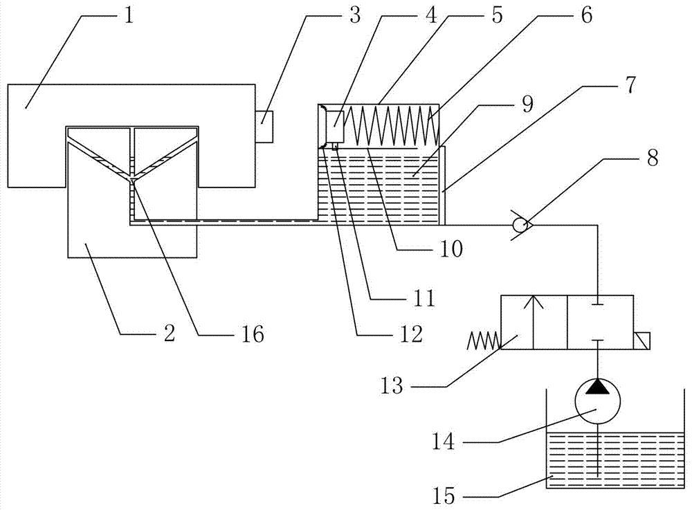
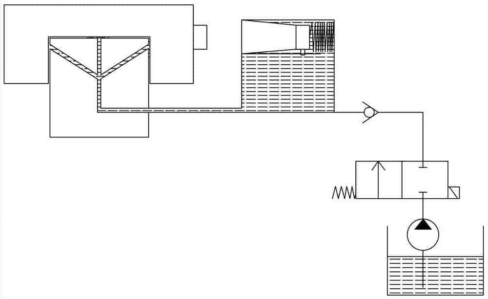
[0020] Such as Figure 1 to Figure 2 As shown, a guide rail automatic lubricating device includes a guide rail 2, a slider 1 adapted to the guide rail 2, the side of the slider 1 is provided with a first magnetic piece 3, and the magnetic pole direction of the first magnetic piece 3 is perpendicular to On the side of the slider 1, at least one through hole 16 is provided on the top and / or side of the guide rail 2, the through hole 16 extends to the bottom or side of the guide rail 2 and is connected to a pipeline, and the other end of the pipeline is connected to the bottom of the oil storage tank, The oil storage tank includes an oil chamber 9 and a pressure chamber 5, a partition 10 is arranged in the middle, a slot is provided in the partition 10, a movable guide 11 is provided in the slot, and...


PUM


Abstract

The invention provides an automatic lubricating device for a guide rail. The automatic lubricating device for the guide rail comprises the guide rail and a sliding block matched with the guide rail. Afirst magnetic component is arranged on the side face of the sliding block. The magnetic pole direction of the first magnetic component is perpendicular to the side face of the sliding block. At least one through hole is formed in the guide rail and extends to the side face of the guide rail to be connected with a pipeline. The other end of the pipeline is connected with an oil storage tank. Theoil storage tank comprises an oil chamber and a pressure chamber. A partition plate is arranged between the oil chamber and the pressure chamber. A liquid level detection device is arranged in the oilchamber. A communication port is formed between the oil chamber and the pressure chamber. An elastic component and a second magnetic component are arranged in the pressure chamber. A guide componentis fixedly connected to the side face of the second magnetic component. A seal structure is arranged between the second magnetic component and the pressure chamber. The magnetic pole direction of thesecond magnetic component is perpendicular to the side face of the sliding block. A one-way valve, an electromagnetic valve, a hydraulic pump and an oil tank are further connected into the oil storagetank. The liquid level detection structure, the electromagnetic valve and the hydraulic pump are all connected with a PLC. By adoption of the structure, the adding quantity of lubricating oil can becontrolled, and all lubricating oil can be added between the guide rail and the sliding block without being wasted.

Description

technical field [0001] The invention relates to the technical field of automation equipment, in particular to an automatic lubricating device for guide rails. Background technique [0002] Lubrication refers to adding grease to reduce the friction between objects, so that the objects are easy to move. Lubrication is a technical measure to improve the friction state of the friction pair to reduce friction resistance and slow down wear. Lubrication is generally achieved through lubricants; lubricants also It has the functions of rust prevention, vibration reduction, sealing, power transmission, etc. Making full use of modern lubrication technology can significantly improve the performance and life of the machine and reduce energy consumption. [0003] In the prior art, manual operation is usually adopted, and lubricating grease is added directly at the position where the slider and the guide rail are in contact. However, it is not only troublesome to add lubricating grease dur...

Claims


Application Information

Patent Timeline
IPC IPC(8): F16C29/02F16N7/14F16N19/00F16N23/00F16N29/02
CPCF16C29/02F16N7/14F16N19/006F16N23/00F16N29/02
Inventor 陈炳祥
Owner JINHUA JINGYING TECH SERVICE CO LTD
Why Eureka
Try Eureka