Bunching device

A wire harnessing and wire splitting technology, which is applied in the manufacture of electrical components, circuits, cables/conductors, etc., can solve the problem of poor winding quality of wire harness holes and wire split holes, difficulty in adjusting the distance between the wire splitting shaft and the wire harness shaft, and inability to meet the needs Adjust the tension of the wire harness and other issues to achieve the effect of fast and efficient winding, cost saving, and convenient adjustment

Inactive Publication Date: 2018-05-08
安徽电信实业集团有限公司器贸分公司
View PDF6 Cites 5 Cited by
  • Summary
  • Abstract
  • Description
  • Claims
  • Application Information

AI Technical Summary

Problems solved by technology

The traditional wire splitting shaft is not easy to disassemble, which causes a lot of inconvenience during the installation process of the device, and the ordinary wire harness device is not easy to adjust the distance between the wire splitting shaft and the wire harness shaft, and the tension of the wire harness cannot be adjusted according to the needs, which affects the quality of the wire harness forming. And ordinary wire harness devices are not suitable for cables of different thicknesses, and the general wire harness holes and wire splitting holes are of low winding quality

Method used


Image

  • Bunching device
  • Bunching device
  • Bunching device

Examples


Embodiment Construction

[0022] The following will clearly and completely describe the technical solutions in the embodiments of the present invention with reference to the accompanying drawings in the embodiments of the present invention. Obviously, the described embodiments are only some, not all, embodiments of the present invention. Based on the embodiments of the present invention, all other embodiments obtained by persons of ordinary skill in the art without making creative efforts belong to the protection scope of the present invention.

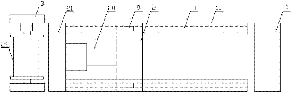
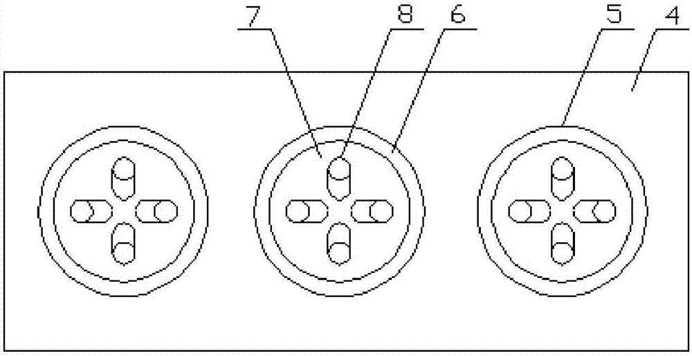
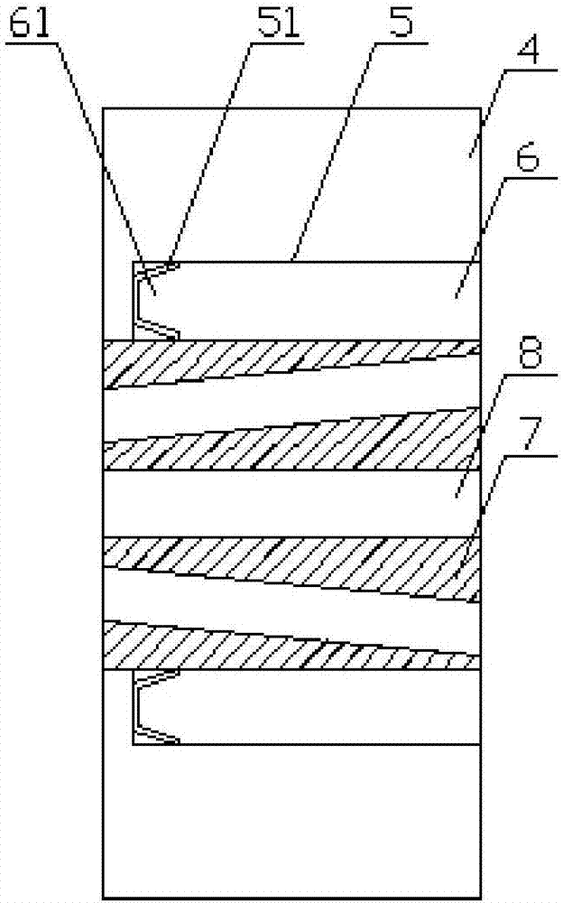
[0023] according to figure 1 , figure 2 and Figure 4 A wire harnessing device shown includes a wire splitting mechanism 1, a wire harnessing mechanism 2 and a wire winding mechanism 3, the wire harnessing mechanism 2 is arranged on one side of the wire splitting mechanism 1, and the wire winding mechanism 3 is arranged on the wire harness On one side of the mechanism 2, the branching mechanism 1 includes a branching case 4, and the branching case 4 is prov...


PUM


Abstract

The invention discloses a bunching device comprising a branching mechanism, a bunching mechanism and a winding mechanism. The bunching mechanism is arranged at one side of the branching mechanism; andthe winding mechanism is arranged one side of the bunching mechanism. The branching mechanism includes a branching shell with a mounting slot; a first bearing is arranged inside the mounting slot; awire arrangement block is arranged inside the first bearing; and through holes are formed in the wire arrangement block. According to the bunching device, because the groove is in a spiral shape, on the one hand, a composite wire fixation effect is realized by cooperation of the groove with the wound composite wire, so that a phenomenon that the winding is not compact because of sliding of multiple strands of single wires during rotation of the bunching hole and thus the cable winding quality is affected can be avoided; and on the one hand, the spiral groove and the composite wire cooperate with each other to drive conveying of the composite wire when the bunching hole is rotating and multiple groups of cables can be wound simultaneously under cooperation of a first gear, a second gear, and a third gear based on setting of a plurality of bunching holes and through holes, so that the bunching device is used conveniently with reduced energy consumption and lowered costs.

Description

technical field [0001] The invention relates to the field of wire harness devices, in particular to a wire harness device. Background technique [0002] In the field of cable manufacturing, a wire harness device is often used. The wire harness device is a device used to twist multiple single wires into a composite wire. The device is often equipped with a wire harness shaft for gathering wires and a wire splitting shaft for splitting wires. , the single-strand wires pass through the through-holes on the thread-splitting shaft in turn, and then pass through the through-holes on the beam-splitting shaft together, through the rotation of the thread-splitting shaft, multiple strands of single wires are twisted into composite wires. The traditional wire splitting shaft is not easy to disassemble, which causes a lot of inconvenience during the installation process of the device, and the ordinary wire harness device is not easy to adjust the distance between the wire splitting shaf...

Claims


Application Information

Patent Timeline
Patent Type & Authority Applications(China)
IPC IPC(8): H01B13/02
CPCH01B13/02H01B13/0207H01B13/0285
Inventor 陆军陈礼晨姚磊
Owner 安徽电信实业集团有限公司器贸分公司
Why Eureka
Try Eureka