
Design method of panel structure of double-sided solar battery tracking bracket

A technology of solar cells and double-sided cells is applied to the support structure, electrical components, photovoltaic modules and other directions of photovoltaic modules, which can solve the problems of loss of solar radiation and limited gain of radiation, and achieve good gain effect, simple and reliable structure, The effect of increasing the amount of solar radiation

Inactive Publication Date: 2018-05-08
STATE GRID HUBEI ELECTRIC POWER COMPANY +3
View PDF5 Cites 2 Cited by
  • Summary
  • Abstract
  • Description
  • Claims
  • Application Information

AI Technical Summary

Problems solved by technology

Bifacial batteries placed horizontally or at a certain inclination angle cannot fully utilize the characteristics of power generation on both sides of the front and back. Although bifacial batteries placed vertically make effective use of the power generation characteristics of the front and back sides of the bifacial battery, they abandon Radiant energy at noon when the sun is at its strongest
[0003] There are also some installation methods that try to install a flat reflector or a curved reflector under the double-sided battery to increase the radiation on the reverse side of the double-sided battery. However, since the double-sided battery is fixed, it will inevitably lose a lot of solar radiation. And Due to the change of the angle of the sun's rays, the radiation gain provided by the fixed reflector to the reverse side of the double-sided cell through reflection is also limited.

Method used


Image

  • Design method of panel structure of double-sided solar battery tracking bracket
  • Design method of panel structure of double-sided solar battery tracking bracket
  • Design method of panel structure of double-sided solar battery tracking bracket

Examples


Embodiment Construction

[0054] The technical solutions of the present invention will be further described below in conjunction with the drawings and specific embodiments.

[0055] The inventive method comprises steps:

[0056] Step 1, analyze and explain the general structure of the support panel of this design, explain the main functions of each part, and the applied principle knowledge.

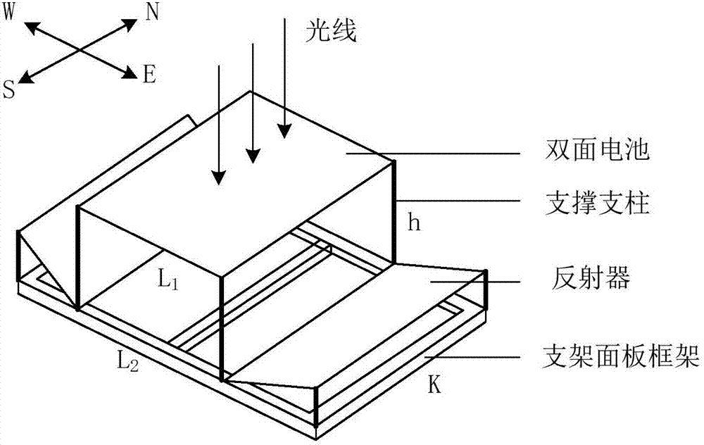
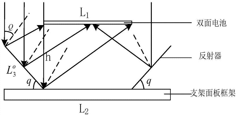
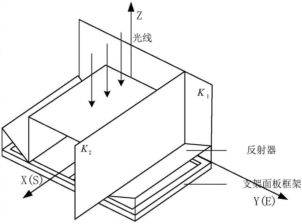
[0057] Such as figure 1 As shown, on the bracket panel frame, raise the double-sided battery to a height of h, fix it with 4 supporting pillars, and install a mirror with a certain inclination angle (inclination angle range 0-90°) on each side of it as a reflector, left and right The function of the reflector is to change the direction of propagation of the direct light irradiated on its surface through reflection, so that it finally directly shines on the back of the double-sided battery. The double-sided battery is raised, which is not only conducive to air circulation, helps the battery components to dissipat...


PUM


Abstract

The invention discloses a design method of a double-sided solar battery bracket panel which is applied to a tracking bracket and is added with reflector structures. Based on the power generation performance of front and back sides of a double-sided solar battery and the optical principle, the invention provides a design method of a panel structure of a double-sided solar battery tracking bracket.The method comprises the steps of (1) analyzing a general structure of a designed bracket panel and local latitude and longitude, sunshine and climate conditions, (2) determining the size data of thedouble-sided battery and the distance between bracket panel frames, and designing initial sizes and inclination angles of two reflectors at left and right sides of the double-sided solar battery, and(3) designing certain size margins for the two reflectors with the consideration of the change of the angle between direct sunlight and the double-sided battery to improve the amount of radiation received by the battery, and finally determining the size data of the whole bracket panel. According to the method, the overall structure of the bracket panel can be flexibly designed according to a localenvironment, the size of the double-sided battery and the like, and the amount of radiation received by the double-sided battery can be significantly increased.

Description

technical field [0001] The invention relates to the technical field of panel structure design of a solar tracking support, in particular to a method for designing a panel structure of a double-sided solar cell support with a reflector structure. Background technique [0002] Since both sides of the double-sided solar cell can generate electricity, and the power generation performance of the reverse side is only slightly weaker than that of the front side, the application of double-sided solar cells is becoming more and more extensive. However, generally double-sided batteries are mostly used in fixed brackets, or placed horizontally, or placed at a certain angle, or placed vertically. The double-sided battery placed horizontally or at a certain inclination angle cannot fully utilize the characteristics of power generation on both sides of the double-sided battery. Radiant energy at noon when the sun is at its strongest. [0003] There are also some installation methods tha...

Claims


Application Information

Patent Timeline
Patent Type & Authority Applications(China)
IPC IPC(8): H02S20/32H02S40/22
Inventor 李大虎孙建波罗俊阳方华亮罗宾刘行波徐文渊邱思齐刘三鑫陶元
Owner STATE GRID HUBEI ELECTRIC POWER COMPANY
Learn More