
A metal pipe welding heat exchange device

A technology for heat exchange devices and metal pipes, applied in welding equipment, auxiliary equipment, auxiliary welding equipment, etc., can solve the problems of affecting the metal structure of the weld, poor cooling effect, uneven preheating, etc., and achieve good wetting effect, Improved welding efficiency and improved flow conditions

Active Publication Date: 2019-08-02
中国石油天然气第一建设有限公司
View PDF5 Cites 0 Cited by
  • Summary
  • Abstract
  • Description
  • Claims
  • Application Information

AI Technical Summary

Problems solved by technology

The traditional pipeline preheating methods include flame heating and electric heating, but there are disadvantages of uneven preheating and high cost; traditional inter-channel temperature control mostly adopts natural cooling or cooling with wet rags. There are shortcomings such as long waiting time, low welding efficiency, and sluggish labor. When using a wet rag to cool down, there are shortcomings such as poor cooling effect and affecting the metal structure of the weld.

Method used


Image

  • A metal pipe welding heat exchange device
  • A metal pipe welding heat exchange device
  • A metal pipe welding heat exchange device

Examples


Embodiment 1

[0033] Take pipes with a nominal diameter of DN100 to DN150 as an example:

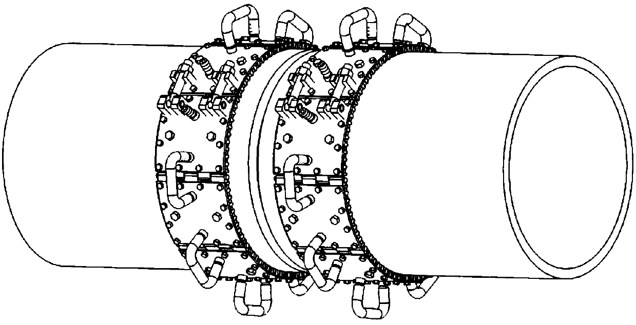
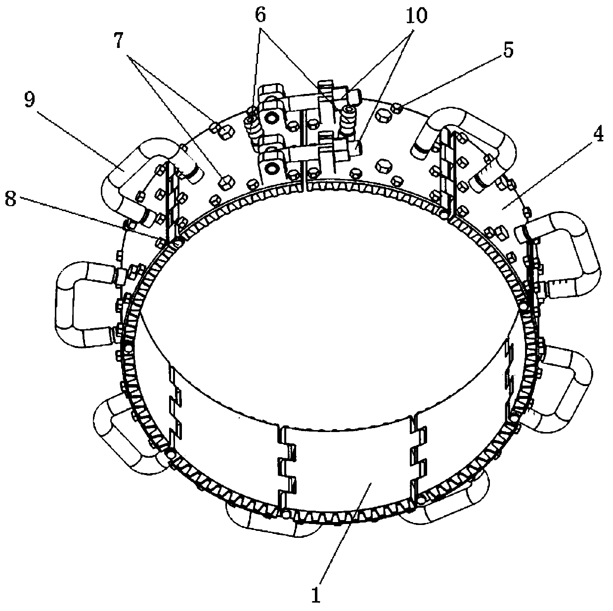
[0034] as attached Figure 1-5 As shown, a metal pipe welding heat exchange device of this patent includes multi-section arc-shaped plate heat exchange fins, inter-node connecting pins 8 , inter-node connecting pipes 9 and adjusting bolts 10 .

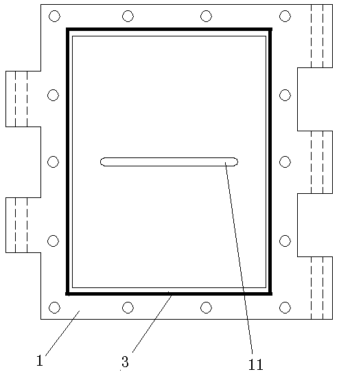
[0035] The arc-shaped plate heat exchanger includes arc-shaped copper plate 1, foam copper 2, sealing ring 3, arc-shaped stainless steel shell 4 and compression bolt 5; The outer side of the arc-shaped red copper plate 1; the width of the arc-shaped red copper plate 1 is 80 mm, the arc diameter is ø140, and the arc length is 86 mm.

[0036] A water tank is provided in the central area of ​​the outer arc surface of the arc-shaped red copper plate 1, and a 2 mm reinforcing rib 11 is provided inside the water tank along the arc direction; a sealing groove is provided on the frame of the water tank, and a sealing ring 3 is arranged in the sealing groove; foam cop...

Embodiment 2

[0041] Embodiment 2 has the same technical solution as Embodiment 1, but adopts an arc-shaped red copper plate 1 with an arc diameter of ø325 and an arc length of 85 mm, which is suitable for pipes with a nominal diameter of DN200-DN350.

Embodiment 3

[0043] The technical solution of embodiment 3 is also the same as that of embodiment 1. The arc-shaped red copper plate 1 with an arc diameter of ø508 and an arc length of 159 mm is used to adapt to pipes with a nominal diameter above DN400.


PUM


Abstract

The invention discloses a heat exchange device for welding of a metal pipeline. The heat exchange device comprises multiple sections of arc-shaped plate type heat exchange pieces, inter-section connecting pins, inter-section connecting pipes and adjusting bolts; each arc-shaped plate type heat exchange piece comprise an arc-shaped red copper plate, foam copper, a sealing ring, an arc-shaped stainless steel casing and compression bolts; the multiple sections of arc-shaped plate type heat exchange pieces are in chained connection through the inter-section connecting pins; the inter-section connecting pipes are arranged at water inlets / outlets of the adjacent arc-shaped stainless steel casings correspondingly; the adjusting bolts are arranged on the last section of arc-shaped plate type heatexchange piece after chained connection and is connected with the first section of arc-shaped plate type heat exchange piece so as to fix the whole heat exchange device for welding of the metal pipeline to the outer wall of the pipeline. The heat exchange device has the beneficial effects as follows: the arc-shaped red copper plates are closely attached to the outer wall of the pipeline, the contact surface is large, and the heat exchange efficiency is high; and the heat exchange device can adapt to welding of pipelines in various different diameters, has the wide application range and is convenient to mount and dismount, the equipment cost is saved, and the production efficiency is improved.

Description

technical field [0001] The invention relates to the technical field of pipe welding, in particular to a metal pipe welding heat exchange device. Background technique [0002] When welding metal pipes, in order to ensure the welding quality and reduce welding cracks, there are strict requirements on the welding temperature in many cases: for example, when the wall thickness of carbon steel and low alloy steel is greater than a certain thickness, it must be preheated before welding; austenitic stainless steel, aluminum And aluminum alloy, titanium and titanium alloy, nickel-based nickel alloy, zirconium and zirconium alloy welding must strictly control the interpass temperature (interpass temperature ≤ 100 ℃ or 150 ℃), etc. The traditional pipeline preheating methods include flame heating and electric heating, but there are disadvantages of uneven preheating and high cost; traditional inter-channel temperature control mostly adopts natural cooling or cooling with wet rags. Th...

Claims


Application Information

Patent Timeline
Patent Type & Authority Patents(China)
IPC IPC(8): B23K37/00B23K101/06
CPCB23K37/00B23K37/006
Inventor 张俊生管松军姚海盛卫建良何永明郭超李建波慕香奎刘素李清君杨国庆李星郑大宝孙利国陈厌灾祁茂金扶小军
Owner 中国石油天然气第一建设有限公司
Learn More