A tire mold side plate and tire mold
A tire mold and side plate technology, applied in the field of tire manufacturing, can solve problems such as tire rubber hair, and achieve the effects of sufficient exhaust, uniform distribution and good exhaust effect
- Summary
- Abstract
- Description
- Claims
- Application Information
AI Technical Summary
Problems solved by technology
Method used
Image
Examples
Embodiment 1
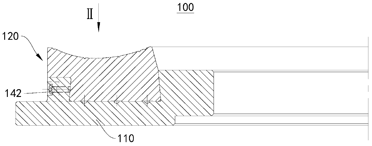
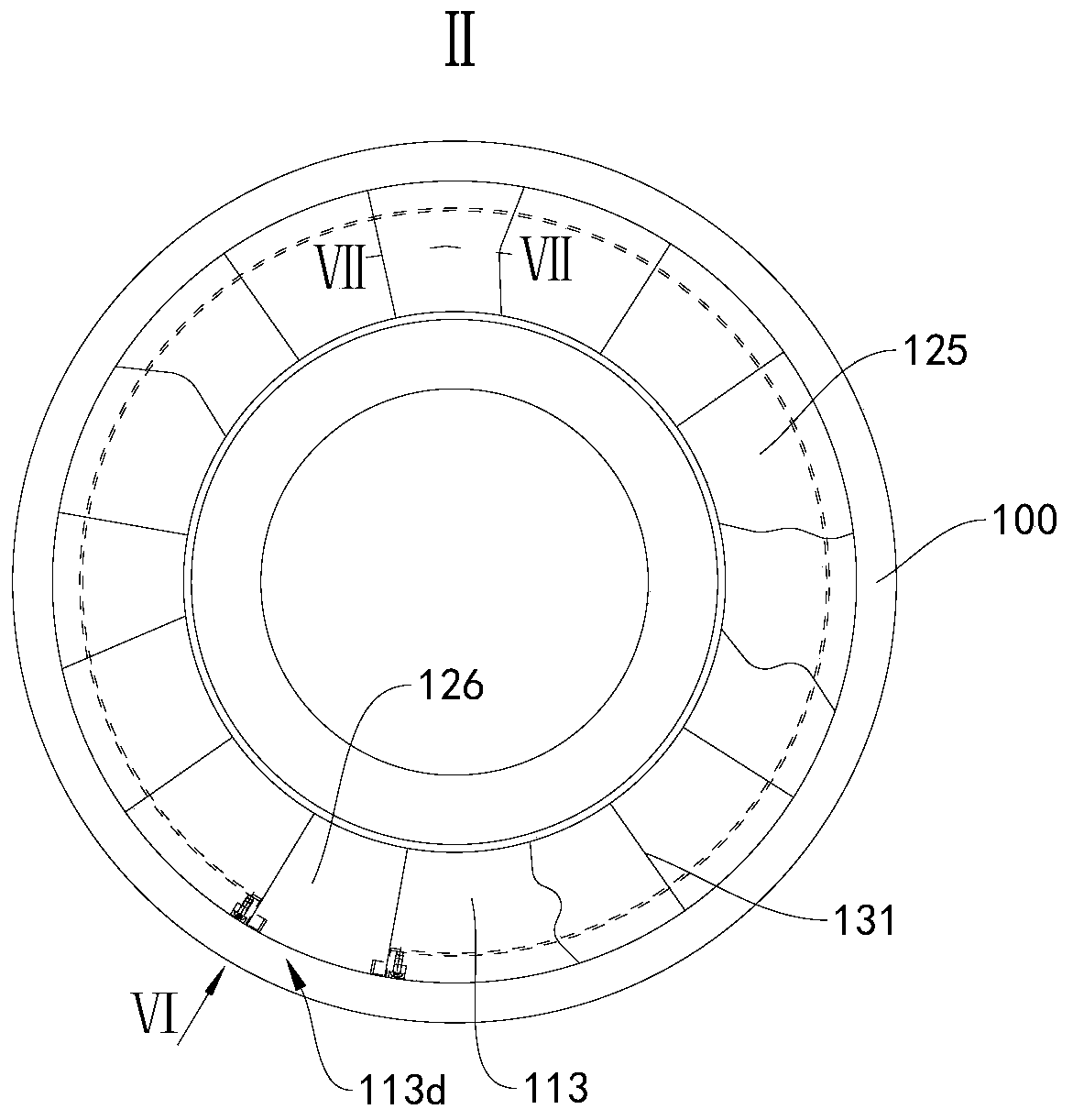
[0054] figure 1 A schematic diagram of a partial cross-sectional structure of the tire mold side plate 100 provided in this embodiment, figure 2 for figure 1 Schematic diagram of the structure in the middle direction. Please refer to figure 1 and figure 2 , the present embodiment provides a tire mold side plate 100, which includes an annular side plate body 110 and a plurality of side plate pieces 120 arranged at intervals along the circumferential direction on the side plate body 110, between adjacent side plate pieces 120 An exhaust passage 131 is formed. The side plate piece 120 is movably matched with the side plate body 110 along the circumferential direction.
[0055] The tire mold side plate 100 provided in this embodiment is further described below:
[0056] image 3 A partial cross-sectional schematic diagram of the side plate body 110 in the tire mold side plate 100 provided in this embodiment. Please refer to image 3 , In this embodiment, the side plate ...
Embodiment 2
[0069] Figure 8 A schematic diagram of a partial cross-sectional structure of the tire mold side plate 100 provided in this embodiment, Figure 9 for Figure 8 Schematic diagram of the middle IX structure, Figure 10 A schematic diagram of a partial cross-sectional structure of the side plate body 110 in the tire mold side plate 100 provided in this embodiment, Figure 11 for Figure 10 Schematic diagram of the middle XI structure, Figure 12 A partial cross-sectional structural schematic diagram of the third side plate 127 in the tire mold side plate 100 provided in this embodiment, Figure 13 The partial cross-sectional structure diagram of the fourth side panel piece 128 in the tire mold side panel 100 provided in this embodiment. Please refer to Figure 8-Figure 13 , the present embodiment also provides a tire mold side plate 100, which is basically the same as that of embodiment 1, except that the way to realize the axial fixation and circumferential movement of th...
Embodiment 3
[0073] Figure 14 A partial cross-sectional structural schematic diagram of the tire mold 010 provided in this embodiment. The tire mold 010 includes an upper cover 011 and a base 012 oppositely arranged. The two sets of tire mold side panels 100 described in Embodiment 1 are fixedly connected to the lower surface of the upper cover 011 and the upper surface of the base 012 respectively. The tire mold 010 also includes a plurality of pattern blocks 013 arranged radially outside the tire mold side plate 100, and a guide ring mechanism 014 for controlling the closure or opening of the pattern blocks 013 during mold opening and closing. Figure 14 In this case, the tire mold 010 is in a mold clamping state, and the pattern blocks 013 and two sets of tire mold side plates 100 together form a mold cavity 015 . During the working process of the tire mold 010, the gas in the mold cavity 015 enters the exhaust groove 131b through the exhaust gap 131a, collects into the circumferenti...
PUM
 Abstract
Description
Claims
Application Information
 - R&D
- Intellectual Property
- Life Sciences
- Materials
- Tech Scout
- Unparalleled Data Quality
- Higher Quality Content
- 60% Fewer Hallucinations
Browse by: Latest US Patents, China's latest patents, Technical Efficacy Thesaurus, Application Domain, Technology Topic, Popular Technical Reports.
© 2025 PatSnap. All rights reserved.Legal|Privacy policy|Modern Slavery Act Transparency Statement|Sitemap|About US| Contact US: help@patsnap.com


