Shading tape and display device

A technology of shading tape and tape, applied in the direction of adhesives, film/sheet adhesives, etc., can solve the problems of reliability test wrinkles, achieve good creep and stability, improve product yield, and reduce costs.

Pending Publication Date: 2018-05-11
BOE TECH GRP CO LTD +1
View PDF6 Cites 3 Cited by
  • Summary
  • Abstract
  • Description
  • Claims
  • Application Information

AI Technical Summary

Problems solved by technology

[0003] The technical problem to be solved by the embodiments of the present invention is to provide a light-shielding tape and a display device to solve the technical problem of product wrinkles in the reliability test

Method used


Image

  • Shading tape and display device
  • Shading tape and display device
  • Shading tape and display device

Examples


no. 1 example

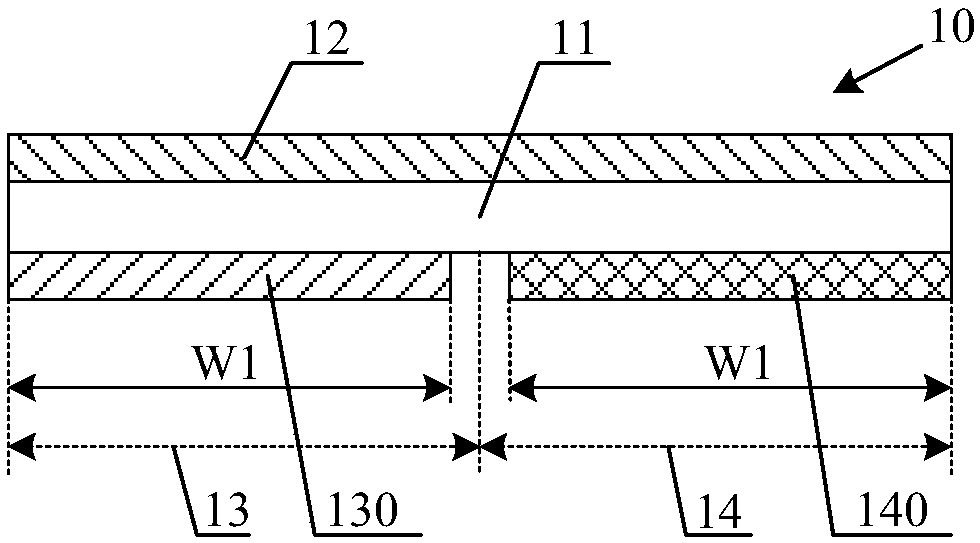
[0036] figure 1 It is a structural schematic diagram of the light-shielding tape according to the first embodiment of the present invention. from figure 1 It can be seen from the figure that the light-shielding adhesive tape 10 includes an adhesive tape body 11 and a first adhesive layer 12 disposed on the first surface of the adhesive tape body 11 . The second surface of the adhesive tape body 11 facing away from the first surface has a first region 13 and a second region 14 that do not intersect each other. The second adhesive layer 130 is disposed in the first area 13 , and the third adhesive layer 140 is disposed in the second area 14 , and the third adhesive layer 140 has creepability and non-transferability. figure 1 The first area 13 and the second area 14 shown in fig.

[0037] figure 2 It is a schematic structural diagram of a display device using a light-shielding tape according to the first embodiment of the present invention. When the light-shielding tape 10 ...

no. 2 example

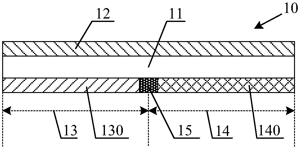
[0044] image 3 It is a schematic structural diagram of the light-shielding adhesive tape according to the second embodiment of the present invention. This embodiment is an extension of the first embodiment, and the main structure of the light-shielding tape in this embodiment is the same as that of the first embodiment. In this embodiment, a light-blocking tape 15 is disposed between the second surface of the adhesive tape body 11 and between the second adhesive layer 130 and the third adhesive layer 140 .

[0045] like figure 2 As shown, when the light-shielding tape of the first embodiment is applied to the display device, since there is a certain gap between the plastic frame 40 and the backlight module 30, there will be a gap between the plastic frame 40 and the backlight module 30 on the second surface of the light-shielding tape. Gap area between groups of 30. The gap area is located between the second adhesive layer 130 and the third adhesive layer 140 . In actual...

no. 3 example

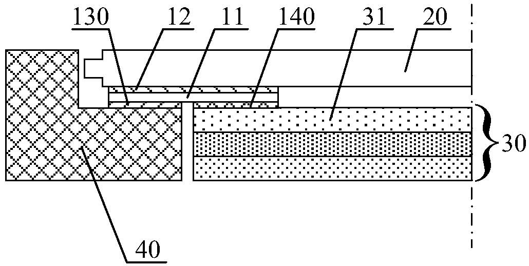
[0047] Figure 4 It is a schematic structural diagram of a display device according to the third embodiment of the present invention. from Figure 4 It can be seen from the figure that the display device includes a plastic frame 40, a backlight module 30 disposed on the same side as the plastic frame 40, and a display panel 20 located above the backlight module 30, and the display device also includes the above-mentioned light-shielding tape 10, The light-shielding tape 10 is sandwiched between the plastic frame 40 , the backlight module 30 and the display panel 20 . Wherein, the second surface of the adhesive tape body 11 faces the plastic frame 40 and the backlight module 30, the surface of the plastic frame 40 is pasted to the second adhesive layer 130, the surface of the backlight module 30 is pasted to the third adhesive layer 140, and the surface of the display panel 20 The surface is pasted to the first adhesive layer 12 .

[0048] Those skilled in the art understand...


PUM

PropertyMeasurementUnit
thicknessaaaaaaaaaa

Abstract

The invention discloses a shading tape and a display device. The shading tape comprises a tape body, a first adhesive layer arranged on the first surface of the tape body as well as a second adhesivelayer and a third adhesive layer which are arranged on the second surface of the tape body; the second adhesive layer and the third adhesive layer are arranged on a first area and a second area correspondingly; and the third adhesive layer has wriggling property and non-transfer property. The display device comprises the shading tape; the surface of an adhesive frame adheres to the second adhesivelayer; the surface of a backlight module adheres to the third adhesive layer; and the surface of a display panel adheres to the first adhesive layer. Due to the wriggling property and the stability of the third adhesive layer, the third adhesive layer does not influence thermal expansion and cold contraction of the film layer of a backlight module membrane layer, the membrane layer is effectivelyprevented from generating wrinkle in a reliability test, and the yield of products is increased. Due to the non-transfer property of the third adhesive layer, the third adhesive layer is not liable to transfer to the membrane layer, the membrane layer is prevented from being stained and the production cost is reduced.

Description

technical field [0001] The invention relates to the field of display technology, in particular to a light-shielding adhesive tape and a display device. Background technique [0002] During the manufacturing process of the display device, it is necessary to use a light-shielding tape to bond the plastic frame, the backlight module and the display panel together. The plastic frame and the backlight module are located on the lower side of the shading tape, and the display panel is located on the upper side of the shading tape. Therefore, the adhesive layers on the upper and lower sides of the light-shielding tape are required to have good viscosity in order to play a good connection. However, during the reliability test, since the upper film layer of the backlight module is completely fixed by the adhesive layer of the light-shielding tape, the thermal expansion and contraction performance of the upper film layer is affected, and wrinkles are prone to occur, which reduces the ...

Claims


Application Information

Patent Timeline
Patent Type & Authority Applications(China)
IPC IPC(8): C09J7/20
CPCC09J2203/318C09J2301/124C09J2301/208C09J2301/21C09J2301/312
Inventor 储汉奇蔡斯特郑亮亮
Owner BOE TECH GRP CO LTD
Why Eureka
Try Eureka