Irrigation ditch dredging equipment for water conservancy irrigation

A technology for cleaning equipment and silt, applied in the direction of earth mover/shovel, construction, etc., can solve the problems of low working intensity, high silt removal work intensity, easy to get on the human body, etc., to avoid the effect of cleaning

Active Publication Date: 2018-05-11
内蒙古恒源水利工程有限公司
View PDF4 Cites 8 Cited by
  • Summary
  • Abstract
  • Description
  • Claims
  • Application Information

AI Technical Summary

Problems solved by technology

[0005] In order to overcome the current disadvantages that the sludge cannot be used in situ when removing the sludge from the irrigation ditches used for water conservancy irrigation, the work intensity of sludge removal is high, and it is easy to stick to the human body, the technical problem to be solved by the present invention is to provide It is a kind of irrigation ditch sludge cleaning equipment for water conservancy irrigation, which utilizes the sludge on the spot and uses equipment to remove the sludge, which has low work intensity and high efficiency, and is not easy to get on the human body.

Method used


Image

  • Irrigation ditch dredging equipment for water conservancy irrigation
  • Irrigation ditch dredging equipment for water conservancy irrigation
  • Irrigation ditch dredging equipment for water conservancy irrigation

Examples


Embodiment 1

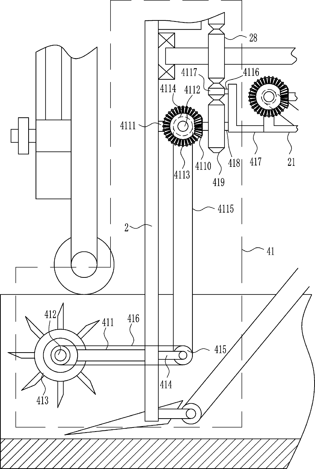
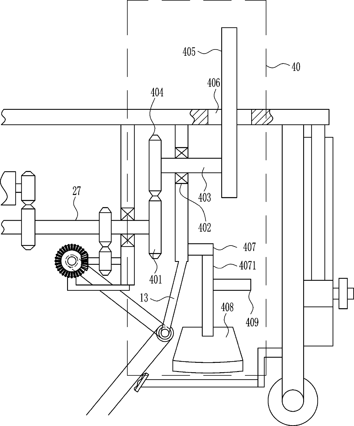
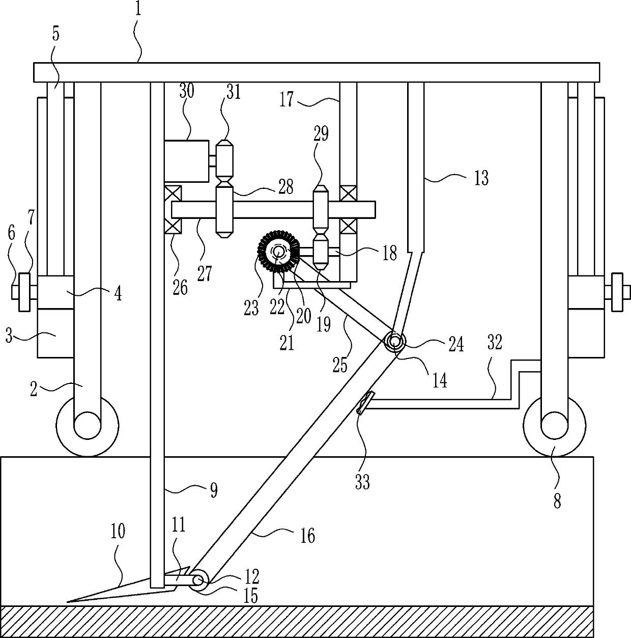
[0027] A kind of irrigation ditch sludge cleaning equipment for water conservancy irrigation, such as Figure 1-5 As shown, it includes top plate 1, support rod 2, slide rail 3, slider 4, push rod 5, nut 6, screw rod 7, wheel 8, first connecting rod 9, bucket 10, first connecting block 11, the first One rotating shaft 12, inclined bar 13, second rotating shaft 14, first runner 15, conveyor belt 16, second connecting rod 17, the third rotating shaft 18, the first circular gear 19, the first bevel gear 20, the first L-shaped rod 21, the fourth rotating shaft 22, the second bevel gear 23, the second runner 24, the first transmission bar 25, the first bearing seat 26, the first rotating rod 27, the second circular gear 28, the third Circular gear 29, the first motor 30, the 4th circular gear 31, place plate 32 and brush block 33, top plate 1 lower side, left and right front side four positions are provided with support bar 2, and support bar 2 upper ends are not connected with top...

Embodiment 2

[0029] A kind of irrigation ditch sludge cleaning equipment for water conservancy irrigation, such as Figure 1-5As shown, it includes top plate 1, support rod 2, slide rail 3, slider 4, push rod 5, nut 6, screw rod 7, wheel 8, first connecting rod 9, bucket 10, first connecting block 11, the first One rotating shaft 12, inclined bar 13, second rotating shaft 14, first runner 15, conveyor belt 16, second connecting rod 17, the third rotating shaft 18, the first circular gear 19, the first bevel gear 20, the first L-shaped rod 21, the fourth rotating shaft 22, the second bevel gear 23, the second runner 24, the first transmission bar 25, the first bearing seat 26, the first rotating rod 27, the second circular gear 28, the third Circular gear 29, the first motor 30, the 4th circular gear 31, place plate 32 and brush block 33, top plate 1 lower side, left and right front side four positions are provided with support bar 2, and support bar 2 upper ends are not connected with top ...

Embodiment 3

[0032] A kind of irrigation ditch sludge cleaning equipment for water conservancy irrigation, such as Figure 1-5 As shown, it includes top plate 1, support rod 2, slide rail 3, slider 4, push rod 5, nut 6, screw rod 7, wheel 8, first connecting rod 9, bucket 10, first connecting block 11, the first One rotating shaft 12, inclined bar 13, second rotating shaft 14, first runner 15, conveyor belt 16, second connecting rod 17, the third rotating shaft 18, the first circular gear 19, the first bevel gear 20, the first L-shaped rod 21, the fourth rotating shaft 22, the second bevel gear 23, the second runner 24, the first transmission bar 25, the first bearing seat 26, the first rotating rod 27, the second circular gear 28, the third Circular gear 29, the first motor 30, the 4th circular gear 31, place plate 32 and brush block 33, top plate 1 lower side, left and right front side four positions are provided with support bar 2, and support bar 2 upper ends are not connected with top...


PUM


Abstract

The invention relates to water conservancy equipment, in particular to irrigation ditch dredging equipment for water conservancy irrigation. By adoption of the irrigation ditch dredging equipment forwater conservancy irrigation, sludge can be used locally, the work intensity of dredging is low, the dredging efficiency is high, and sludge is unlikely to be splashed onto the bodies of workers. Theirrigation ditch dredging equipment for water conservancy irrigation comprises a top plate, supporting rods and the like. The supporting rods are arranged under the left side, the right side, the front side and the rear side of the top plate correspondingly, and the upper ends of the supporting rods are not connected with the top plate. According to the irrigation ditch dredging equipment for water conservancy irrigation, sludge can be used locally, the work intensity of dredging is low, and the dredging efficiency is high; and sludge is primarily collected from ditches through a bucket and then conveyed by a conveying belt so as to be thrown into farmland around, so that sludge is locally used, and sludge in the ditches can be completely cleared away.

Description

technical field [0001] The invention relates to water conservancy equipment, in particular to an irrigation ditch sludge cleaning equipment for water conservancy irrigation. Background technique [0002] At present, when removing the silt of irrigation ditches for water conservancy irrigation, most of them use manual hand-held tools to remove the silt from the ditch, but the disadvantage of this is that it is difficult to remove the silt thoroughly, and in the process of removal, The work is very intensive, and the removed sludge also needs to be transported to other places for utilization. [0003] Therefore urgently need to research and develop a kind of can utilize silt on the spot, adopt equipment to remove silt and work intensity is high in efficiency, and the irrigation ditch silt cleaning equipment for water conservancy irrigation that is not easy to get on the body of manpower is needed to overcome the current cleaning of irrigation ditch for water conservancy irriga...

Claims


Application Information

Patent Timeline
Patent Type & Authority Applications(China)
IPC IPC(8): E02F5/28E02F7/02
CPCE02F5/28E02F7/026
Inventor 钱东涂晨妍蔡亚茜
Owner 内蒙古恒源水利工程有限公司
Why Eureka
Try Eureka