Living body testing probe

a testing probe and living body technology, applied in the field of living body testing probes, can solve the problems of affecting the operation of the testing device, occurrence of defects, and inability to easily form openings and the like, so as to reduce the effect of reducing the size of the living body testing prob

Active Publication Date: 2013-06-13
SEIKO EPSON CORP
View PDF8 Cites 2 Cited by
  • Summary
  • Abstract
  • Description
  • Claims
  • Application Information

AI Technical Summary

Benefits of technology

[0011]In the living body testing probe, the display part preferably serves as the non-mechanical switch part. Specifically, by using the display part as a touch panel (non-mechanical switch), the size of the living body testing probe can be reduced compared to a case in which the switch is provided separately from the display part.
[0012]In the living body testing probe, the notification part preferably includes a signal output section configured and arranged to output an operation signal via a wire. With this configuration, the living body testing probe may be connected to a main testing device via the wire, and the test conditions may be changed in the main testing device. Accordingly, since the living body testing probe does not need to have a drive circuit and the like necessary for driving in the living body testing probe, the size of the living body testing probe can be reduced.
[0013]In the living body testing probe, the non-mechanical switch part is preferably an optical switch. With this configuration, liquid-tight properties of the switch can easily be achieved.
[0014]The optical switch is preferably an infrared switch configured and arranged to be operated by light emission and light reception of infrared light. This configuration has an advantage that outside light will not easily affect an operation with the switch.
[0015]In the living body testing probe, the non-mechanical switch part is preferably provided in a protruded area protruding with respect to a region surrounding the non-mechanical switch part, or in a recessed area recessed with respect to the region surrounding the non-mechanical switch part. With this configuration, the position of the non-mechanical switch can easily be sensed by touch.
[0016]The living body testing probe according to the above described aspect of the present invention may be configured as an ultrasonic probe, for example. In such a case, the living body contact part is configured and arranged to generate and receive ultrasonic waves, for example. In the case of the ultrasonic probe, since the living body contact part is caused to contact a surface of a living body with application of gel, the ultrasonic probe is frequently cleaned. Therefore, the effect of the present invention configured to be suitable for cleaning becomes significant.

Problems solved by technology

The conventional living body testing probes described in the above mentioned publications, however, have a disadvantage that the main testing device needs to be operated with one hand to change the test conditions while operating the living body testing probe with the other hand.
However, since the living body testing probe needs to be cleaned frequently due to its nature, providing a mechanical switch such as a dial switch or a lever switch for changing the test conditions causes a problem that a space or opening created in a movable portion of the mechanical switch is difficult to clean, and water and the like used for cleaning enters the inside of the living body testing probe from the space or opening in the movable portion to the mechanical switch, which easily results in occurrence of a defect.
Further, since the non-mechanical switch that receives operation input for changing test conditions upon being touched or approached is used as the switch, opening and the like will not be easily formed unlike in the case of using a mechanical switch.

Method used


Image

  • Living body testing probe
  • Living body testing probe
  • Living body testing probe

Examples


first embodiment

Overall Configuration

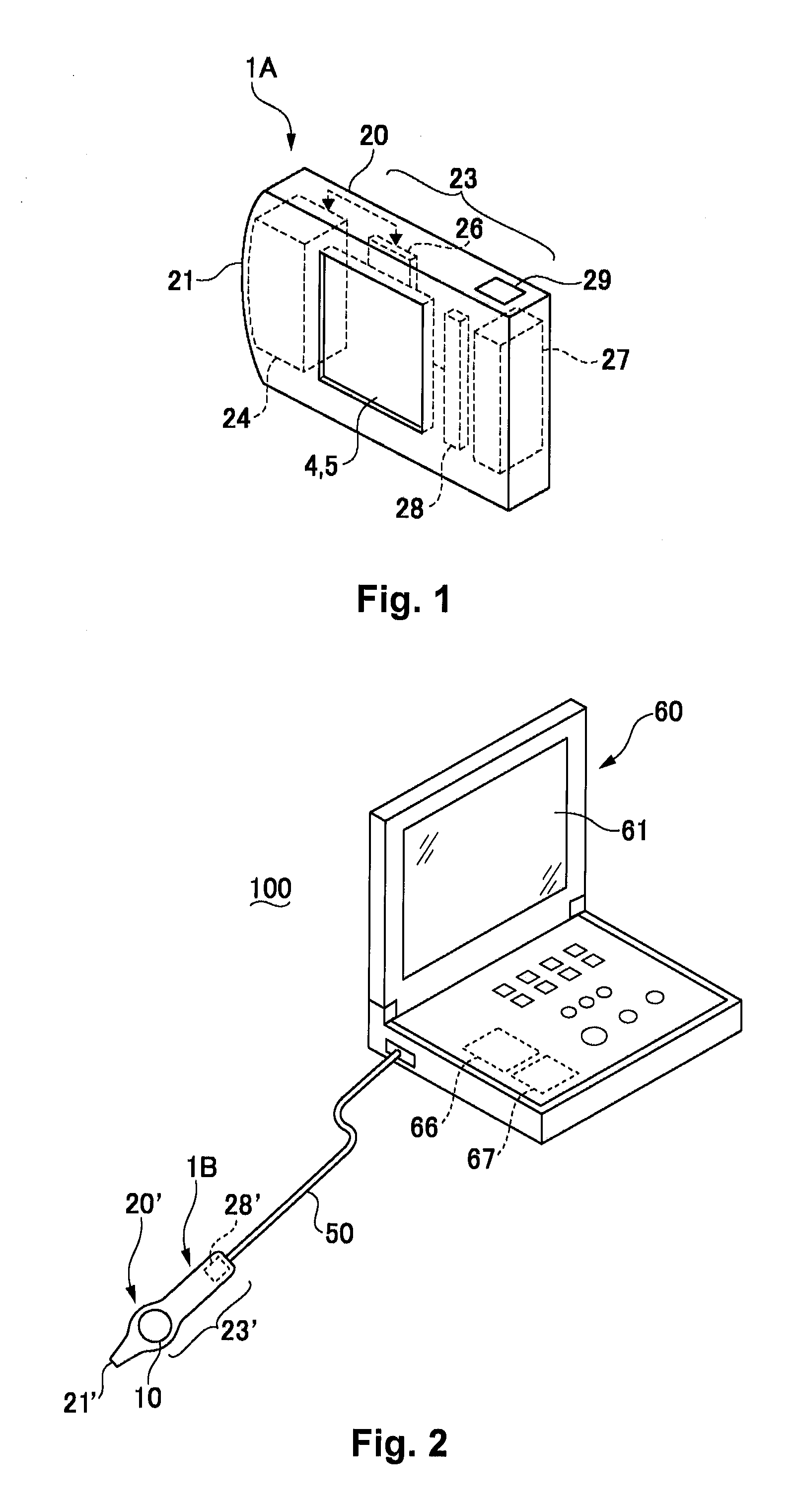
[0025]FIG. 1 is a simplified perspective view of an ultrasonic probe 1A according to a first embodiment of the present invention. In the ultrasonic probe 1A shown in FIG. 1, a probe main body 20 has a generally flattened shape. The probe main body 20 has a living body contact part 21 for contacting the living body at the tip end thereof, and the rest of the probe main body 20 is used as a grip part 23. The tip end of the living body contact part 21 is curved in an arc shape as shown in FIG. 1. An ultrasonic transducer 24, an acoustic lens (not shown in the drawings), and the like are embedded in the living body contact part 21. The ultrasonic transducer 24 is provided with a plurality of elements configured such that an electrode is formed on both surfaces of a thick film of a piezoelectric body such as PZT (piezoelectric zirconate titanate) or polyvinylidene fluoride. When exciting pulses are applied to both the electrodes of this element, the piezoelectric bod...

second embodiment

[0036]Referring now to FIGS. 2 to 5, a living body testing probe in accordance with a second embodiment will now be explained. Since the basic configuration of the present embodiment is similar to that of the first embodiment, the components of the present embodiment that are identical or similar to the components of the first embodiment are indicated with a single prime (′). Moreover, in view of the similarity between the first and second embodiments, the descriptions of the parts of the second embodiment that are similar to the parts of the first embodiment may be omitted for the sake of brevity.

Overall Configuration

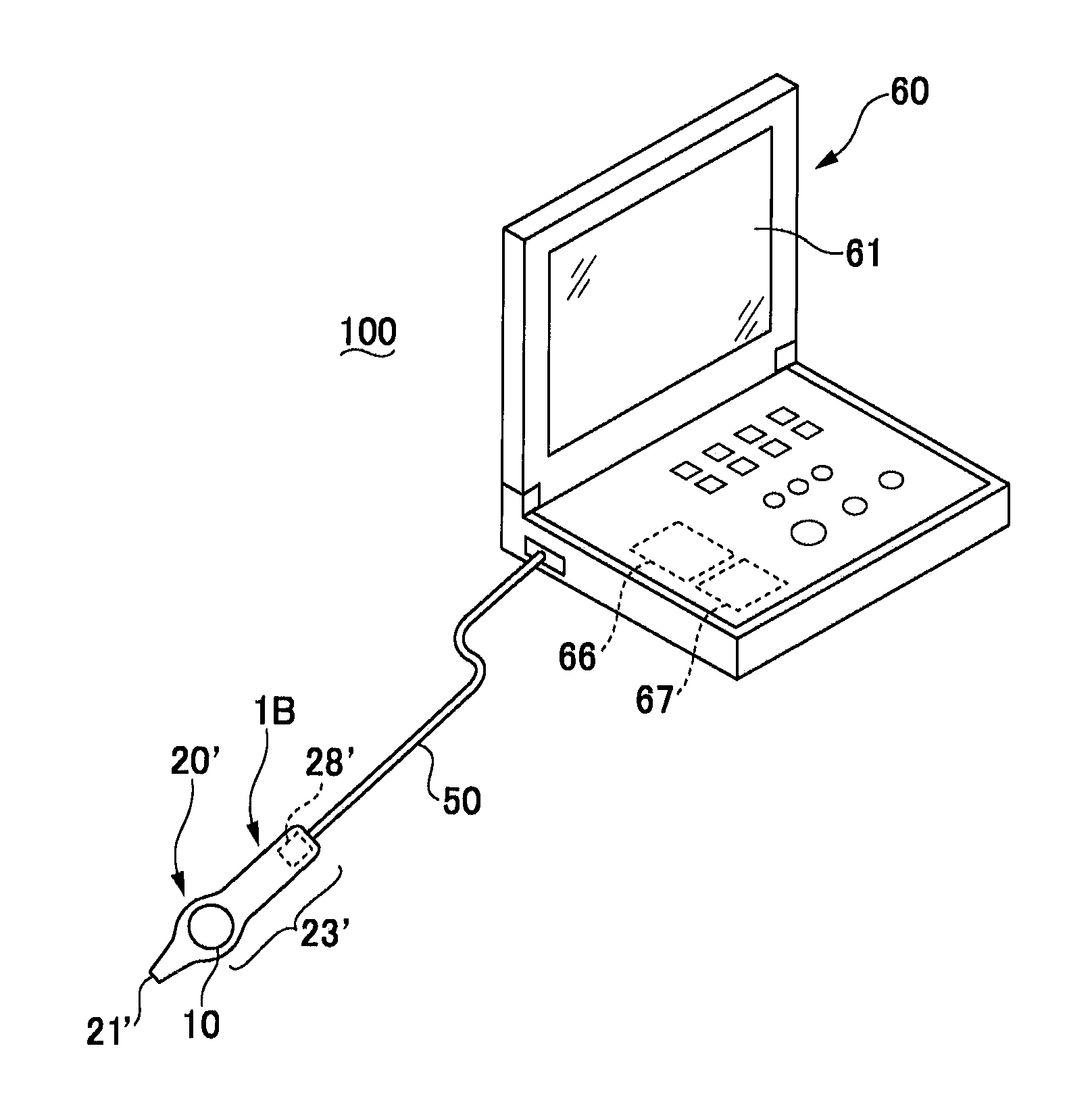
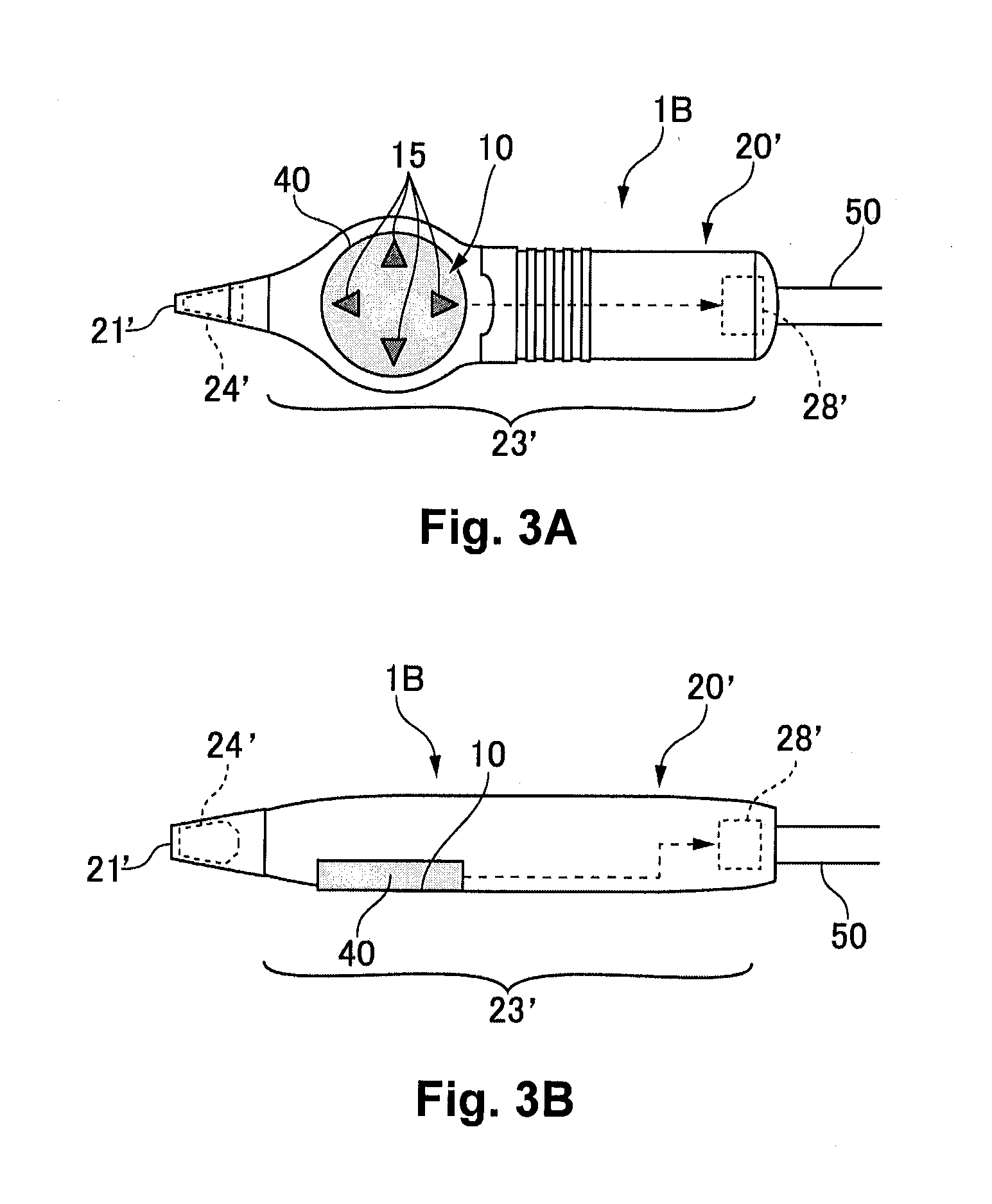
[0037]FIG. 2 is a simplified perspective view of a testing device provided with an ultrasonic probe 1B according to a second embodiment of the present invention. FIGS. 3A and 3B are enlarged views of the ultrasonic probe 1B according to the second embodiment of the present invention. Specifically, FIG. 3A is a top plan view of the ultrasonic probe 1B, and FIG. 3b is a ...

modification example of second embodiment

[0053]FIG. 5 is an explanatory diagram of the switch 10′ provided in the ultrasonic probe 1B according to a modification example of the second embodiment of the present invention.

[0054]The switch 10 explained in the second embodiment may be configured to be in the same plane as an outer circumferential surface of the probe main body 20. In this modification example, the switch 10′ is configured such that the translucent member 40′ is protruded with respect to the outer circumferential surface of the probe main body 20′ as shown in FIG. 5. With this configuration, since the switch 10′ can be configured to be a protruded section, the position of the switch 10′ can easily be sensed by touch.

[0055]When the planar view shape of the translucent member 40′ is a cross shape protruded in an operation direction as shown by arrows 15′, it has an advantage that the operation direction can be sensed by touch. Further, a shallow recessed section 49 may be formed in the center of the translucent m...


PUM


Abstract

A living body testing probe includes a living body contact part, a grip part, a non-mechanical switch part and a notification part. The living body contact part is configured and arranged to contact a living body. The non-mechanical switch part is configured and arranged to receive an operation input for changing test conditions upon being touched or approached. The notification part is configured and arranged to output information indicative of a change in the test conditions based on the operation input received by the non-mechanical switch part.

Description

CROSS-REFERENCE TO RELATED APPLICATIONS[0001]This application claims priority to Japanese Patent Application No. 2011-272131 filed on Dec. 13, 2011. The entire disclosure of Japanese Patent Application No. 2011-272131 is hereby incorporated herein by reference.BACKGROUND[0002]1. Technical Field[0003]The present invention relates to a living body testing probe that conducts a test by contacting a living body.[0004]2. Related Art[0005]As a living body testing probe for testing the inside of a living body, there are an ultrasonic probe in which a test is conducted by using reflection of ultrasonic waves inside a living body, a probe for testing a pulse wave in which a test of a pulse wave is conducted by using reflection of infrared light inside a living body, and the like. Among these living body testing probes, for example, in the ultrasonic probe, an ultrasonic element, an ultrasonic lens section, or the like is disposed in a living body contact part of the probe main body, and the ...

Claims


Application Information

Patent Timeline
Patent Type & Authority Applications(United States)
IPC IPC(8): A61B8/00
CPCA61B8/4455A61B8/462A61B8/467A61B8/4444A61B8/4422
Inventor KIYOSE, KANECHIKANAKANISHI, DAISUKE
Owner SEIKO EPSON CORP
Why Eureka
Try Eureka