
Novel motor wind path structure

A new type of wind circuit technology, applied in the field of motors, can solve the problems of poor cooling effect of motor windings and iron cores, and achieve the effect of improving the cooling effect

Pending Publication Date: 2018-05-11
WOLONG ELECTRIC GRP CO LTD +1
View PDF5 Cites 4 Cited by
  • Summary
  • Abstract
  • Description
  • Claims
  • Application Information

AI Technical Summary

Problems solved by technology

[0004] The purpose of the present invention is to provide a new type of motor air passage structure for the poor cooling effect of the above-mentioned motor windings and iron cores, which can change the walking path of the air passage and improve the cooling effect on the left and right end windings and iron cores

Method used


Image

  • Novel motor wind path structure
  • Novel motor wind path structure

Examples


Embodiment Construction

[0014] The implementation of the present invention will be illustrated by specific specific examples below, and those skilled in the art can easily understand other advantages and effects of the present invention from the contents disclosed in this specification.

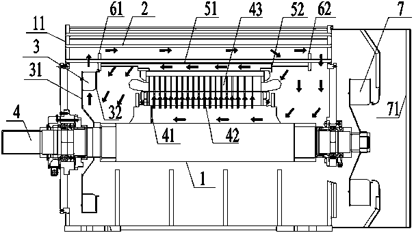
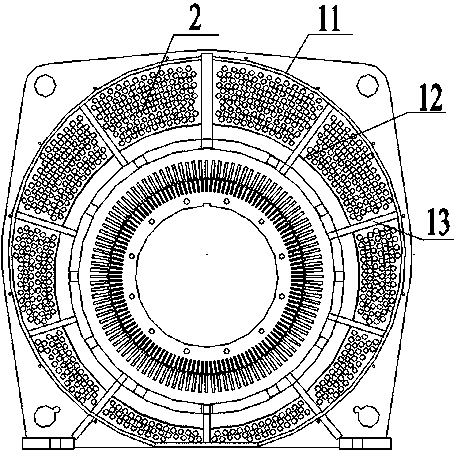
[0015] The present invention provides a new motor air path structure, such as figure 1 with figure 2 As shown, it is especially suitable for flameproof self-lubricating motors (IC511 motors for short). The new motor air duct structure includes a machine base, a cooling pipe 2, an axial rib 13 and an inner fan 3, the machine base includes a machine base body 11, a machine base inner ring 12, and the machine base body 11 and the machine base inner ring 12 There is a cooling cavity in the middle, and a plurality of axial ribs 13 are arranged at intervals along the circumferential direction in the cooling cavity, and each axial rib 13 is fixedly arranged with the machine base. Preferably, the axial ribs 13 are evenly ...


PUM


Abstract

Disclosed is a novel motor wind path structure. The novel motor wind path structure comprises a machine base, cooling pipes, axial rib plates and an inner fan; multiple axial rib plates are arranged on the inner edge of a cooling cavity at intervals in the circumferential direction; multiple cooling pipes are distributed in a hollow cavity between adjacent axial rib plates; the novel motor wind path structure is also provided with an interval ring, a partition plate and an air blocking cylinder; the partition plate is fixedly arranged on a rotary shaft and positioned on the left end part of arotor axial air channel; the air blocking cylinder is fixed with the axial rib plates, and comprises a first air blocking cylinder and a radially-arranged second air blocking plate; an annular wind screen is arranged on the right side in a position, corresponding to the first interval ring, of the inner fan; the wind screen is fixedly connected with the inner fan and rotates along with the inner fan. The novel motor wind path structure, by virtue of setting of the first air blocking cylinder and the second air blocking plate vertically arranged on the right side of the first air blocking cylinder, and the partition plate and the wind screen, can enable the wind path to be routed in the specific path, so that a stator iron core and windings of motors at the left and right end all can be fully ventilated and cooled, and the cooling effect on the windings and the iron core can be improved.

Description

technical field [0001] The invention belongs to the technical field of motors, and in particular relates to a novel motor air passage structure. Background technique [0002] The motor is a conversion device that converts electrical energy into mechanical energy. The working principle of the three-phase asynchronous motor is to energize the stator, the stator generates a rotating magnetic field, and the guide bars of the rotor cut the magnetic field lines, so the rotor is stressed, and the rotor rotates in the direction of the rotating magnetic field of the stator, and finally passes The shaft extension of the rotor transmits torque, which realizes the process of converting electrical energy into mechanical energy. During normal operation of the motor, there are stator losses, rotor losses, iron core losses, mechanical losses, stray losses, etc., and these losses are ultimately in the form of heat in the motor. form manifested. [0003] The 2-pole and 4-pole synchronous spe...

Claims


Application Information

Patent Timeline
Patent Type & Authority Applications(China)
IPC IPC(8): H02K9/06H02K9/08
CPCH02K9/06H02K9/08
Inventor 于树坤余志鹏焦华勇王鑫成李学武赵东娜金红
Owner WOLONG ELECTRIC GRP CO LTD
Learn More