
Dynamic energy-saving speed regulation method and system of permanent magnet synchronous motor

A permanent magnet synchronous motor technology, applied in the direction of AC motor control, control system, electrical components, etc., can solve the problem that the power and running speed of the permanent magnet synchronous motor cannot be effectively self-adapted, and achieve low efficiency and high efficiency. Efficient work, clear logic effect

Active Publication Date: 2018-05-11
SHANGHAI RUKING ELECTRONICS
View PDF5 Cites 0 Cited by
  • Summary
  • Abstract
  • Description
  • Claims
  • Application Information

AI Technical Summary

Problems solved by technology

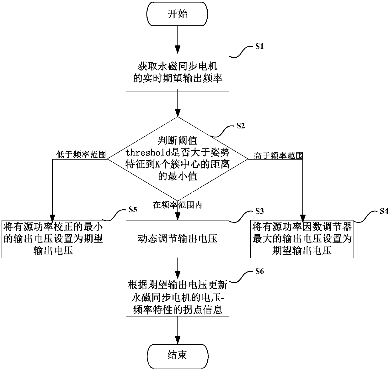
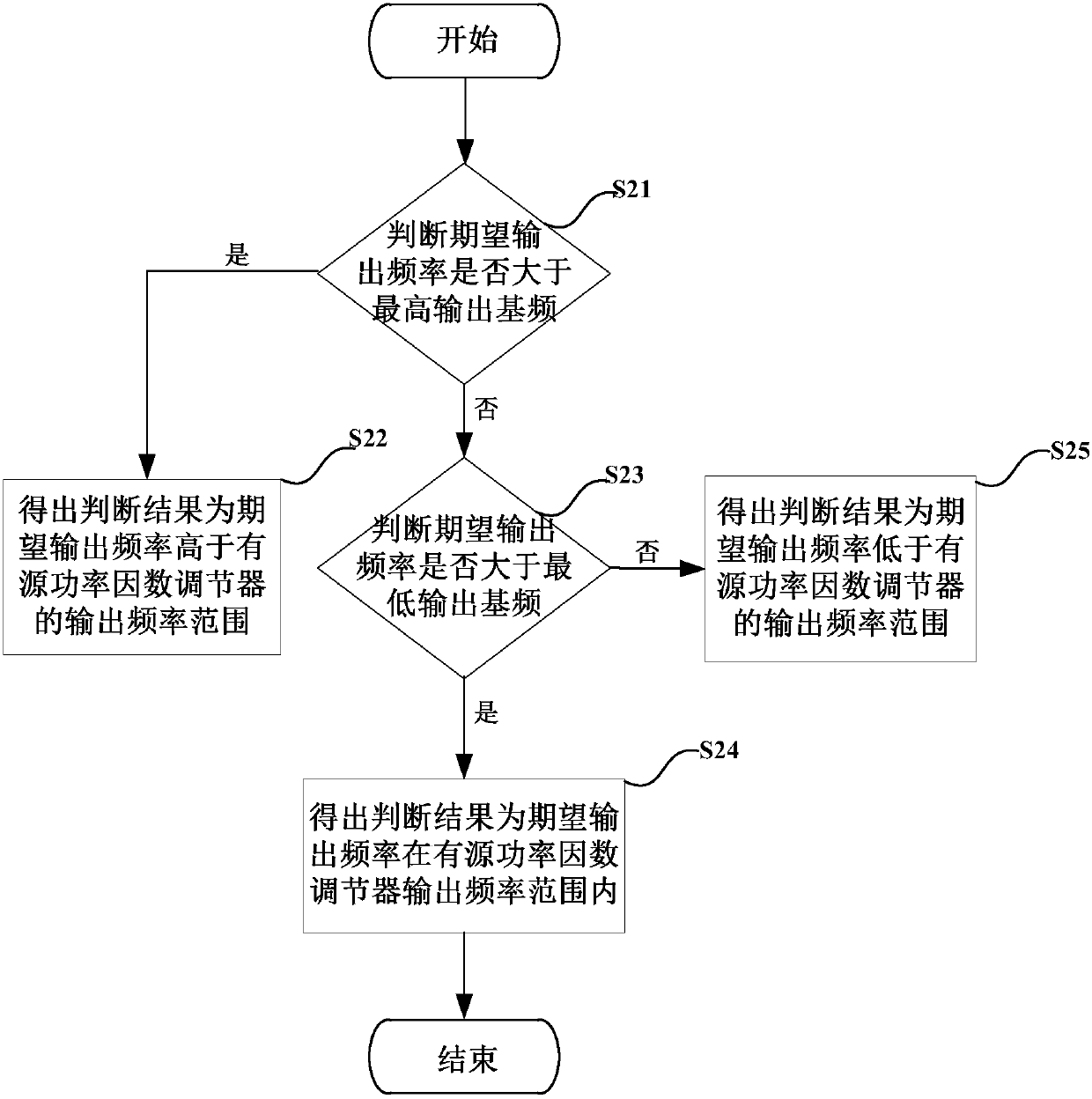
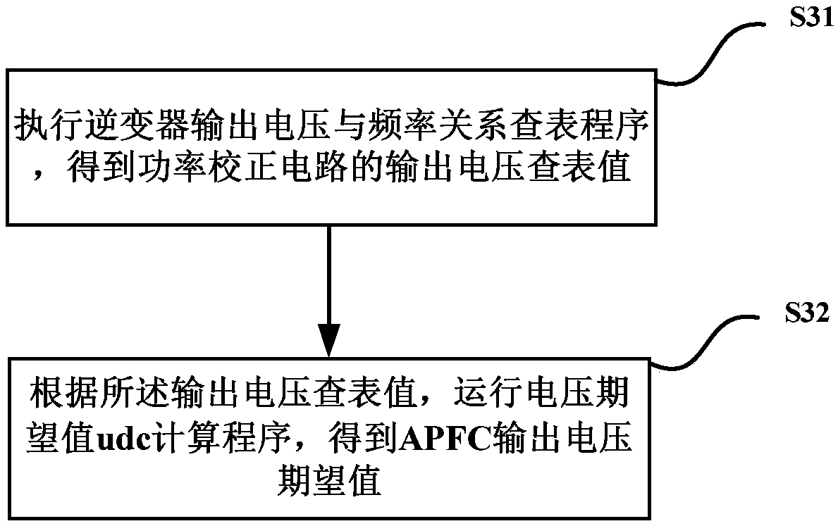
[0004] In view of the above shortcomings of the prior art, the technical problem that the power and operating speed of the permanent magnet synchronous motor cannot be effectively adaptively adjusted in the prior art has not been solved. The purpose of the present invention is to provide a dynamic energy-saving adjustment method for the permanent magnet synchronous motor , including: S1, obtaining the real-time expected output frequency of the permanent magnet synchronous motor; S2, comparing the real-time expected output frequency with the preset output frequency range; S3, if the expected output frequency is within the output frequency range of the active power factor regulator, dynamically Adjust the output voltage; S4, if the desired output frequency is higher than the output frequency range of the active power factor regulator, then set the maximum output voltage of the active power factor regulator as the desired output voltage; S5, if the desired output frequency is lower than the active power factor regulator For the output frequency range of the source power factor regulator, the minimum output voltage of the active power correction is set as the expected output voltage; S6, update the inflection point information of the voltage-frequency characteristic of the permanent magnet synchronous motor according to the expected output voltage

Method used


Image

  • Dynamic energy-saving speed regulation method and system of permanent magnet synchronous motor
  • Dynamic energy-saving speed regulation method and system of permanent magnet synchronous motor
  • Dynamic energy-saving speed regulation method and system of permanent magnet synchronous motor

Examples


Embodiment Construction

[0053] The implementation of the present invention will be illustrated by specific specific examples below, and those skilled in the art can easily understand other advantages and effects of the present invention from the contents disclosed in this specification.

[0054] see Figure 1 to Figure 10 It should be noted that the structures shown in the drawings attached to this specification are only used to cooperate with the content disclosed in the specification for the understanding and reading of those who are familiar with this technology, and are not used to limit the conditions for the implementation of the present invention. Without technical substantive significance, any modification of structure, change of proportional relationship or adjustment of size shall still fall within the technology disclosed in the present invention without affecting the effect and purpose of the present invention. within the scope of the content. At the same time, terms such as "upper", "lo...


PUM


Abstract

The invention relates to a dynamic energy-saving speed regulation method and system of a permanent magnet synchronous motor. The dynamic energy-saving speed regulation method comprises the steps of acquiring a real-time expected output frequency of the permanent magnet synchronous motor; comparing the real-time expected output frequency with a preset output frequency range; if the expected outputfrequency is within the output frequency range of an active power factor regulator, dynamically regulating the output voltage; if the expected output frequency is higher than the output frequency range of the active power factor regulator, setting the maximum output voltage of the active power factor regulator to be the expected output voltage; if the expected output frequency is lower than the output frequency range of the active power factor regulator, setting the minimum output voltage of active power correction to be the expected output voltage; and updating inflection point information ofvoltage-frequency characteristics of the permanent magnet synchronous motor according to the expected output voltage.

Description

technical field [0001] The invention relates to a method and system for dynamic energy-saving adjustment of a permanent magnet synchronous motor. Background technique [0002] The existing permanent magnet synchronous motor is the most important part of the air conditioner, and the traditional fixed speed permanent magnet synchronous motor has relatively large power loss, room temperature fluctuation and noise, so the permanent magnet synchronous motor gradually replaces the traditional fixed frequency and fixed speed permanent magnet synchronous motor. It reduces the number of times the compressor starts and stops, increases the comfort level, and greatly improves the room temperature adjustment effect and energy saving and emission reduction effect. The paper "Application of SVPWM (Space Vector Pulse Width Modulation, Space Vector Pulse Width Modulation) Technology Based on Fuzzy Control in Frequency Conversion and Speed ​​Regulation of Permanent Magnet Synchronous Motors"...

Claims


Application Information

Patent Timeline
IPC IPC(8): H02P27/08H02P27/12H02P25/024
CPCH02P25/024H02P27/085H02P27/12
Inventor 雷淮刚廖原卢广震邓智王小兵邓伟湧
Owner SHANGHAI RUKING ELECTRONICS
Learn More