a terminal device

A technology of terminal equipment and discharge end, which is applied in the field of terminal equipment, can solve problems such as the inability to discharge static electricity in the restricted area of ​​the antenna, the inability to ensure the uniformity of glue dispensing, and the excessive glue in the area, so as to ensure the consistency of electrostatic protection and effective electrostatic protection. Effect

Active Publication Date: 2019-10-18
VIVO MOBILE COMM CO LTD
View PDF8 Cites 0 Cited by
  • Summary
  • Abstract
  • Description
  • Claims
  • Application Information

AI Technical Summary

Problems solved by technology

[0003] However, the above two methods have the following problems: For the first method above, because the width of the brackets at the upper and lower sides of the screen module of the full-screen mobile phone is very small, the screen module will enter the antenna no-space zone of the upper and lower antennas, If the middle frame of the antenna no-go area is made of metal, it will affect the performance of the antenna. Therefore, the middle frame of the antenna no-go area is made of plastic material, which makes it impossible to discharge static electricity at the antenna no-go area; and the above-mentioned second Because the existing manufacturing process cannot guarantee the uniformity of glue dispensing, it will cause more glue and high density in some areas on the side of the screen module, and less glue and low density in some areas, so that the consistency of electrostatic protection cannot be guaranteed.

Method used


Image

  • a terminal device
  • a terminal device
  • a terminal device

Examples


Embodiment 1

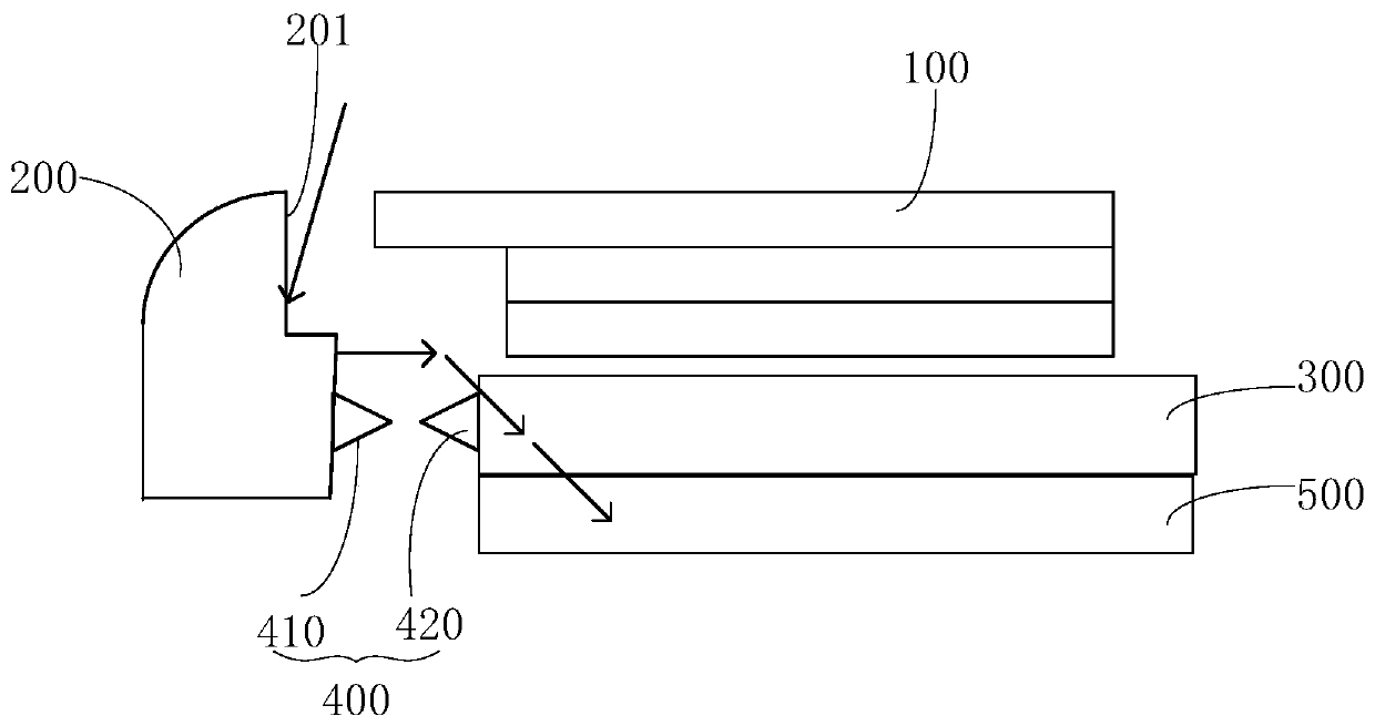
[0039] Such as image 3As shown, in this embodiment, the electrostatic protection structure 400 includes multiple sets of discharge components; each set of discharge components includes: a first discharge terminal 410 disposed on the metal surface of the support 200, the first discharge end 410 A discharge end 410 includes a first sharp portion; and, a second discharge end 420 disposed on the metal middle frame 300, the second discharge end 420 includes a second sharp portion; wherein the first discharge end 410 and the second The discharge ends 420 are arranged at a predetermined distance apart, and the first sharp portion is opposite to the second sharp portion.

[0040] In the above solution, the static electricity protection structure 400 is implemented by using two discharge terminals respectively arranged on the metal surface of the bracket 200 and the metal middle frame 300. When static electricity enters from the side of the screen module 100, due to the The two disch...

Embodiment 2

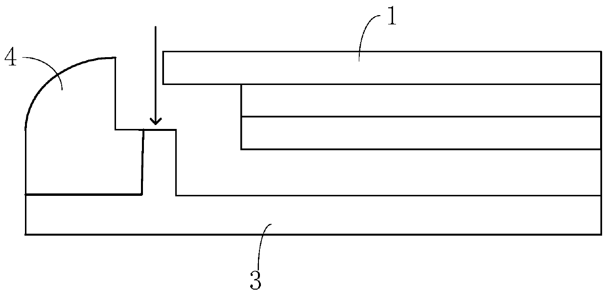
[0048] Such as Figure 4 As shown, in this embodiment, the electrostatic protection structure 400 includes an ESD (Electro-Static discharge, electrostatic discharge) device disposed at the gap between the inner surface 201 of the bracket 200 and the metal middle frame 300 , the ESD device 403 includes a first port and a second port, the first port is connected to the inner surface 201 of the bracket 200 , and the second port is connected to the metal middle frame 300 .

[0049] Using the above solution, the electrostatic protection structure 400 is realized by using the ESD device 403, by connecting the two ports of the ESD device 403 to the metal surface of the bracket 200 and the metal middle frame 300 respectively, when there is static electricity on the side of the screen module 100 When entering, because the first port of the ESD device 403 is in contact with the metal surface of the bracket 200, and the second port of the ESD device 403 is in contact with the metal middl...


PUM


Abstract

The object of the invention is to provide a terminal device. The terminal device comprises a screen module; a bracket disposed on the periphery of the screen module; and a grounded metal middle framelocated on one side of the back face of the screen module; an inner side face of the bracket is a metal surface, and a gap is reversed between the inner surface of the bracket and the metal middle frame; and electrostatic protection structure is arranged between the metal surface of the bracket and the metal middle frame, and the electrostatic protection structure can enable electrostatic conduction between the metal surface of the bracket and the metal middle frame. The electrostatic problem on the side edge of the screen module can be effectively solved, an effective electrostatic protectionfunction can be performed on the side edges of the screen module, and the antenna performance is ensured.

Description

technical field [0001] The present invention relates to the field of display technology, in particular to a terminal device. Background technique [0002] In terminal equipment such as mobile phones, there will be static electricity on the side of the screen module. Such as figure 1 As shown, in a mobile phone with a non-full screen, the way to solve the problem of static electricity on the side of the screen module is to design a ground wire 2 on the outermost edge of the side of the screen module 1 to discharge static electricity. For a full-screen mobile phone, since the side width S of the screen module 1 is very narrow, there is not enough space for wiring. Therefore, at present, the electrostatic protection measures on the side of the screen module of the full-screen model in the industry mainly adopt the following two types: the first one, such as figure 2 As shown, the middle frame 3 is partially extended upwards to be flush with the step surface of the plastic b...

Claims


Application Information

Patent Timeline
Patent Type & Authority Patents(China)
IPC IPC(8): H04M1/02H04M1/18
Inventor 谢进耀
Owner VIVO MOBILE COMM CO LTD
Why Eureka
Try Eureka