Roll stand and method for changing work rolls

A technology for rolling mill stands and work rolls, applied in the direction of metal rolling stands, metal rolling mill stands, metal rolling, etc., capable of solving problems such as complex structures

Active Publication Date: 2018-05-11
SMS GRP GMBH
View PDF9 Cites 4 Cited by
  • Summary
  • Abstract
  • Description
  • Claims
  • Application Information

AI Technical Summary

Problems solved by technology

But this construction is often complex

Method used


Image

  • Roll stand and method for changing work rolls
  • Roll stand and method for changing work rolls
  • Roll stand and method for changing work rolls

Examples


Embodiment Construction

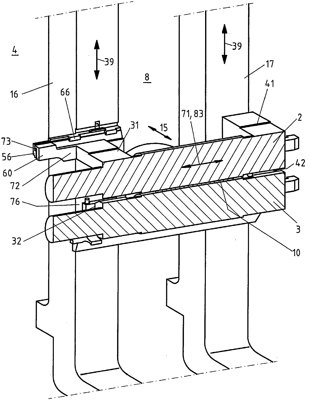
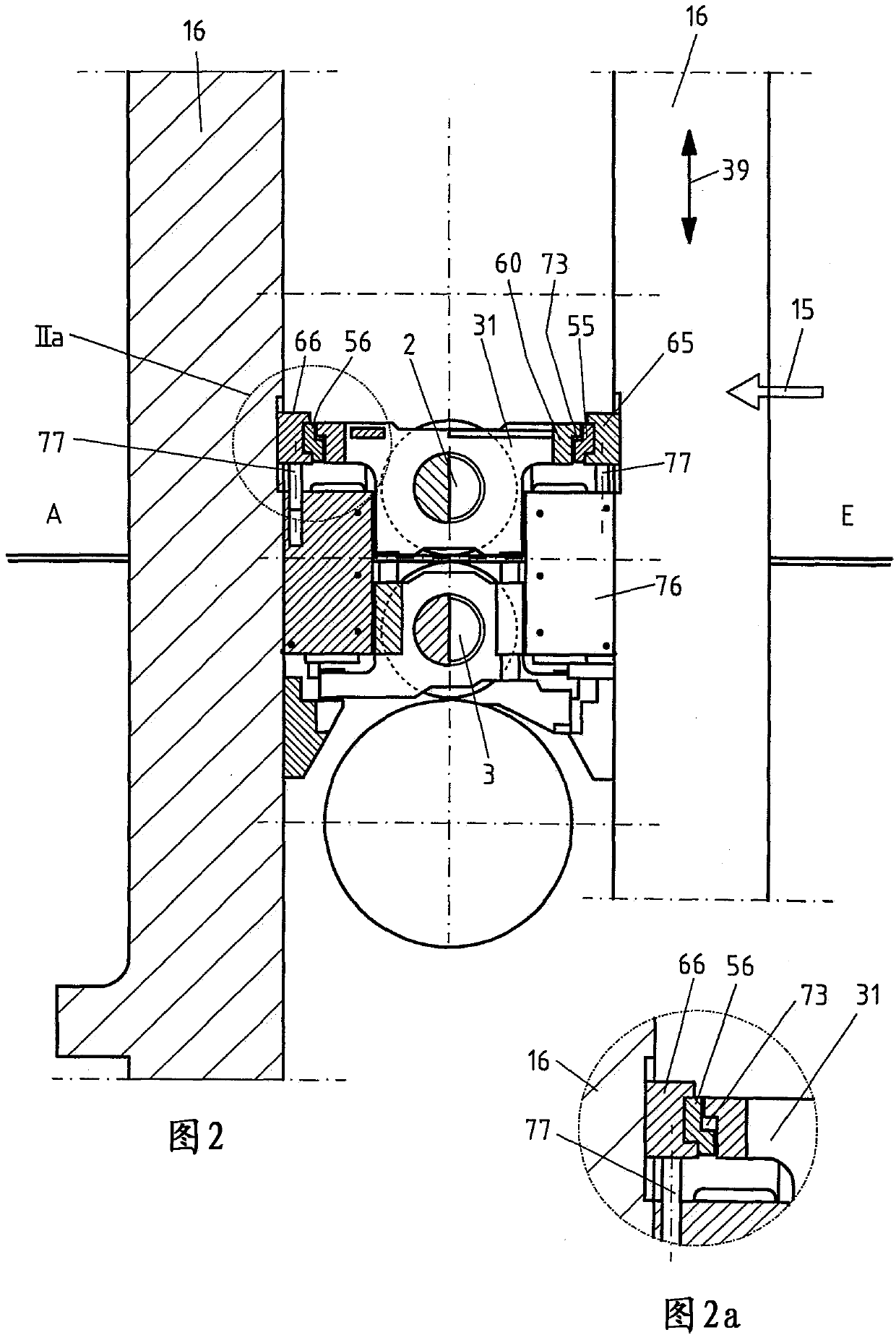
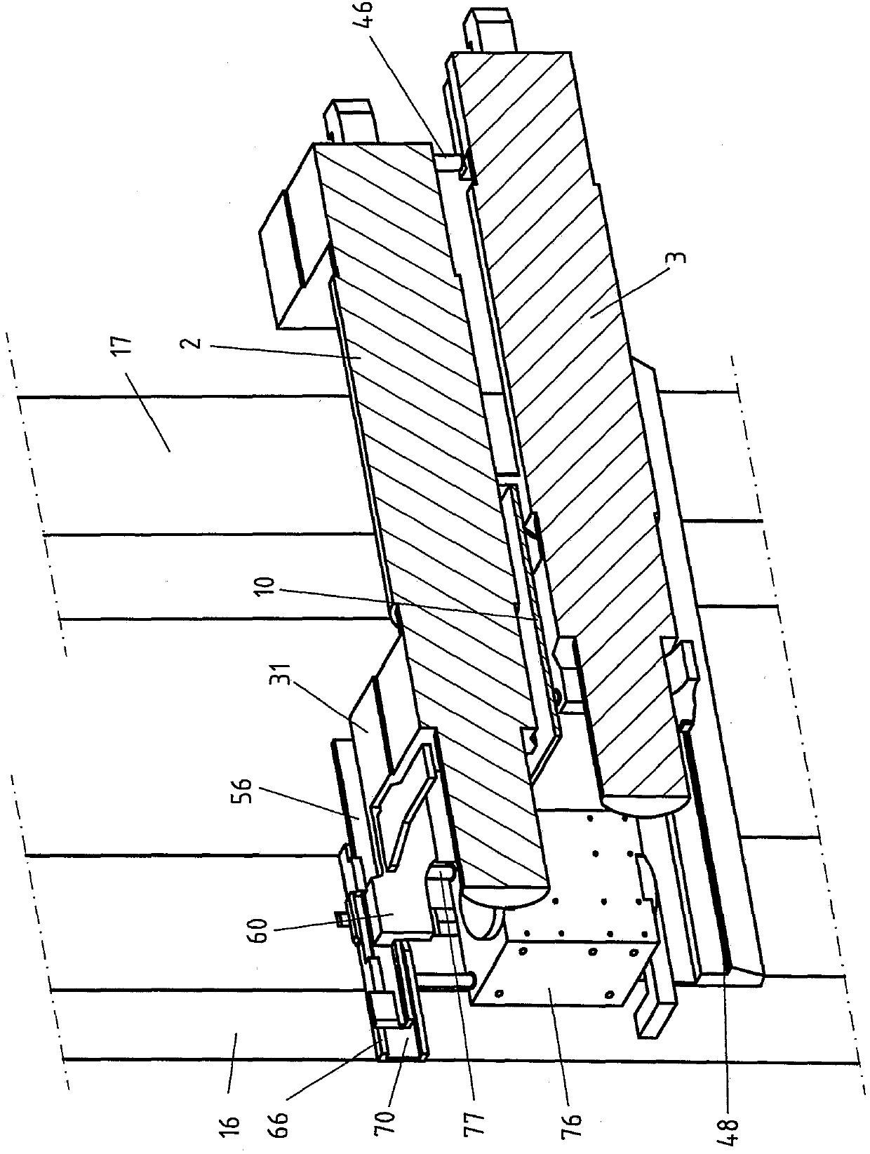
[0050] figure 1 A longitudinal section view of the rolling mill stand 4 is shown. The upper work roll 2 and the lower work roll 3 form a roll pair and form a roll nip at the rolling line 8 in which the rolling stock 10 is rolled. The rolled product 10 is, for example, a flat metal strip.

[0051] The rolling line 8 extends along the rolling direction 15 between the rolling stand column 16 on the drive side of the rolling mill stand 4 and the rolling stand column 17 on the operating side. The rolling stand column 16 on the drive side is characterized in that a drive unit (not shown) for rotationally driving the work rolls 2 and 3 is arranged here.

[0052] The upper work roll 2 is rotatably supported in the mounting member 31 on the driving side and the mounting member 41 on the operating side. Similarly, the lower work roll 3 is rotatably supported in the mounting member 32 on the driving side and the mounting member 42 on the operating side. Mounting pieces 31, 41, 32, 42, also...


PUM


Abstract

The invention relates to a roll stand (4) having work rolls (2, 3) mounted therein. The roll stand has at least one upper mounting rail (55, 56), which is mounted on a drive-side roll stand frame (16)and oriented in a transverse direction to a rolling line (8) running through the roll stand. In order to be able to keep the structure space in the roll stand over the rolling line free during rolling - except for a roll change - and still change the roll efficiently, the upper mounting rail (55, 56) is configured to be moved into the rolling line and out of the rolling line, starting from the drive-side roll stand frame.

Description

Technical field [0001] The present invention relates to a rolling mill stand according to the preamble of claim 1 and a method for replacing work rolls fixed in the rolling mill stand according to the preamble of claims 7 and 9 . The rolling mill stand can be set and applied in cold rolling equipment or hot rolling equipment. The rolling mill stand can be, for example, a Mae-West-Gerüst stand. The rolled product is preferably a metal profile or a metal strip. [0002] In addition, the present invention also relates to a new application mode for the balance cylinder supported on the rolling mill stand, the balance cylinder is usually used to balance the upper support roll. Background technique [0003] According to this type of rolling mill stand capable of changing rolls is known from the prior art. But this structure is usually very complicated. In addition, the work rolls are usually replaced only when there is no longer any material to be rolled in the rolling mill stand, b...

Claims


Application Information

Patent Timeline
Patent Type & Authority Applications(China)
IPC IPC(8): B21B31/10
CPCB21B31/12B21B31/203B21B31/106
Inventor D·冯泰内S·菲舍尔
Owner SMS GRP GMBH
Why Eureka
Try Eureka