
Tower for a wind turbine

A technology for wind power generators and pipe towers, applied in wind power generation, installation/supporting configuration of wind power engines, engine manufacturing, etc., can solve the problems of expensive grid support structure, impact on accessibility, high cost, etc., and achieve simple and reliable Effects of contactability, optimized force transmission, simplified accessibility

Inactive Publication Date: 2018-05-11
THYSSENKRUPP STEEL EURO AG +1
View PDF5 Cites 1 Cited by
  • Summary
  • Abstract
  • Description
  • Claims
  • Application Information

AI Technical Summary

Problems solved by technology

[0006] However, it has been found that such a construction produces significant disadvantages in terms of ergonomics and operational safety, since in particular the accessibility of the individual parts of the tower can be severely affected by the lattice-shaped configuration of the lower tower section
It has also been shown that with such a hybrid construction the construction of the lattice support can be expensive, since it has to withstand high forces and be designed accordingly
This leads to high expenses and high costs

Method used


Image

  • Tower for a wind turbine
  • Tower for a wind turbine
  • Tower for a wind turbine

Examples


Embodiment Construction

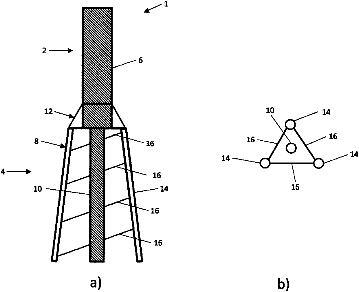
[0042] figure 1 a shows a longitudinal section of a first embodiment of a tower according to the invention, while figure 1 b shows figure 1 a Cross-sectional view of the embodiment shown.

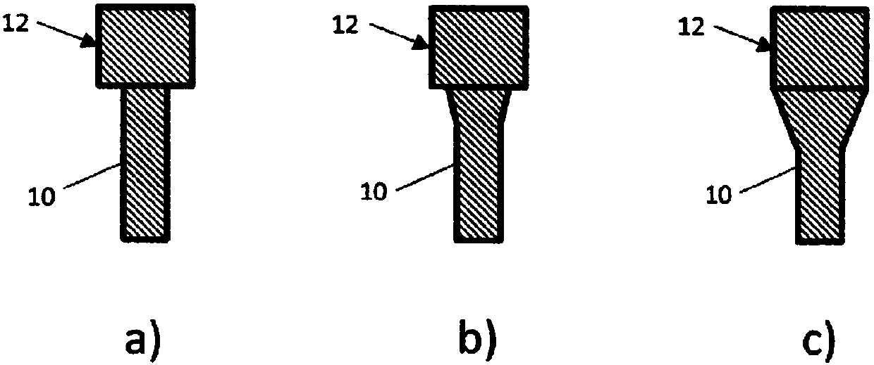
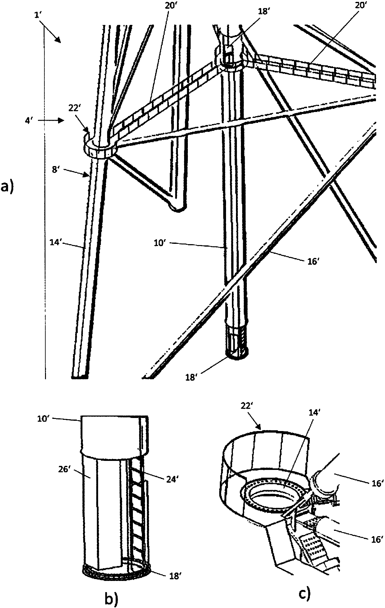
[0043] The tower 1 is part of a wind generator with a nacelle and a rotor (not shown). Column 1 has an upper column section 2 and a lower column section 4 . The upper column section 2 comprises a tube column 6 . The lower tower section 4 comprises a lattice frame 8 and an intermediate pipe 10 which is arranged centrally inside the lattice frame 8 . The intermediate tube 10 generally has a smaller diameter than the tube column 6 of the upper column section 2 . The tower 1 also comprises an intermediate part 12 through which the lattice frame 8, the intermediate pipe 10 and the tube tower 6 are connected to each other. The intermediate pipe 10 is connected at its lower end to the base (not shown) of the column 1 and at its upper end to the intermediate part 12 .

[0044] The central tu...


PUM

PropertyMeasurementUnit
Heightaaaaaaaaaa

Abstract

The invention relates inter alia to a tower for a wind turbine, with an upper tower portion (2) and a lower tower portion (4, 4'), wherein the upper tower portion (2) comprises a tubular tower (6), wherein the lower tower portion (4, 4') comprises a lattice tower (8, 8'). The object of allowing improved ergonomics and work safety and making it possible to obtain a structural design with optimizedforces is achieved by the lower tower portion (4, 4') comprising a central tube (10, 10') arranged centrally within the lattice tower (8, 8'), and by the central tube (10,') having a smaller diameter,at least in certain portions, than at least part of the tubular tower of the upper tower portion.

Description

technical field [0001] The invention relates to a tower for a wind power generator, having an upper tower section and a lower tower section, wherein the upper tower section comprises a tube tower, wherein the lower tower section comprises a lattice frame. The invention also relates to a wind power generator. Background technique [0002] Especially for wind turbines or wind energy generators, especially on land, the trend is towards higher and higher hub heights (the height at which the hub of the wind turbine rotor is located relative to the ground). During this period, heights in excess of 100 meters are desired. As a result, higher and more stable wind speeds can be used, and thus the efficiency of the wind turbine can be improved, especially in weak wind regions. [0003] A taller tower with a larger and more powerful generator or rotor will also result in a larger wall thickness and diameter of the tower section to meet the resulting higher structural mechanics requir...

Claims


Application Information

Patent Timeline
IPC IPC(8): F03D13/20E04H12/00
CPCE02B17/0004E02B17/027E02B2017/0091E04H2012/006F03D13/20F05B2230/30F05B2230/60F05B2240/9121F05B2240/913Y02E10/72Y02E10/728Y02P70/50E04H12/08E04H12/10
Inventor 斯特凡·德鲁斯马克·希尔特洛塔尔·帕特博格阿德里安·帕通帕特里克·特劳卡
Owner THYSSENKRUPP STEEL EURO AG
Features
  • Generate Ideas
  • Intellectual Property
  • Life Sciences
  • Materials
  • Tech Scout
  • Unparalleled Data Quality
  • Higher Quality Content
  • 60% Fewer Hallucinations
Learn More