Sensor device for hydraulic plunger units

A sensor device and sensor technology, which are applied to the components, measuring devices, instruments, etc. of the pumping device for elastic fluid, can solve the problem of high cost, and achieve the effect of cost reduction, multi-function and cost saving.

Active Publication Date: 2018-09-07
ROBERT BOSCH GMBH
View PDF9 Cites 0 Cited by
  • Summary
  • Abstract
  • Description
  • Claims
  • Application Information

AI Technical Summary

Problems solved by technology

The greater the number of sensors here, the higher the cost

Method used


Image

  • Sensor device for hydraulic plunger units
  • Sensor device for hydraulic plunger units
  • Sensor device for hydraulic plunger units

Examples


Embodiment Construction

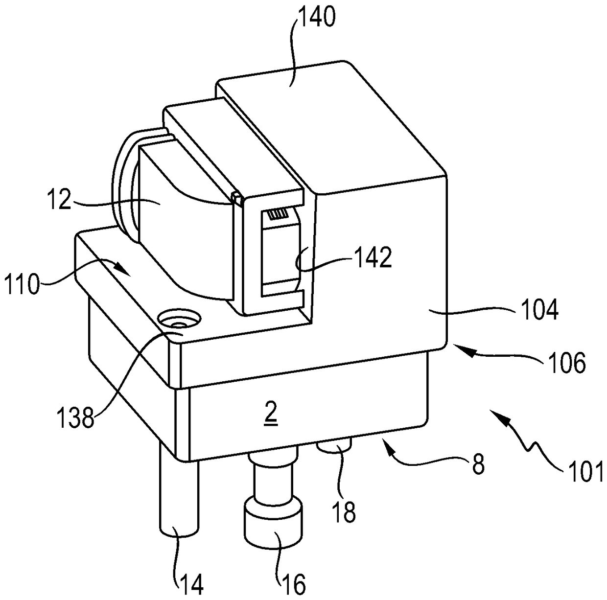
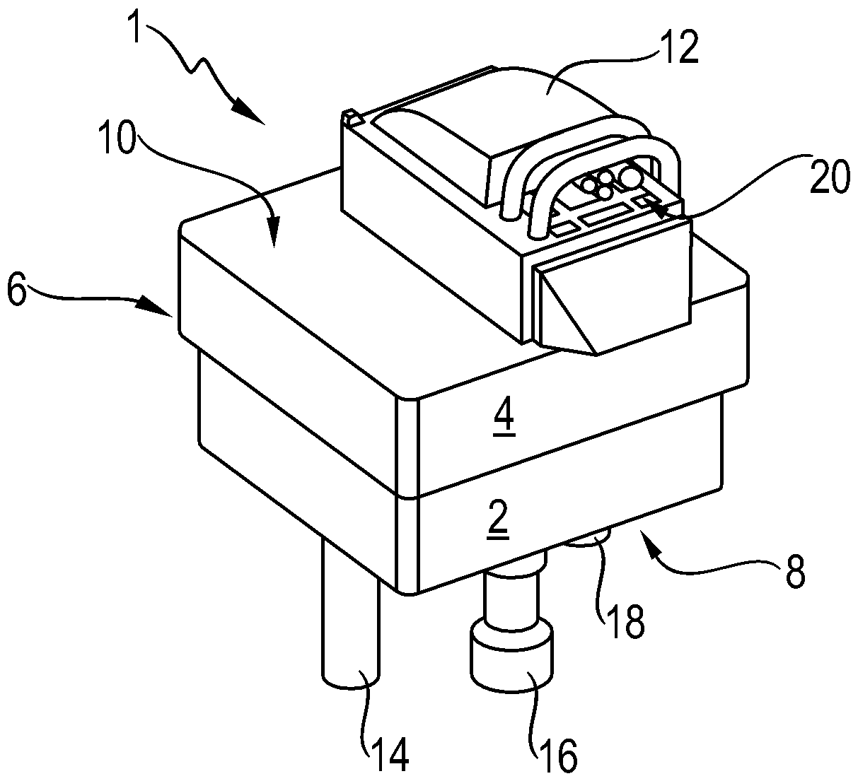
[0035] according to figure 1 , the sensor device 1 has a sensor housing 6 of approximately rectangular cross-section with a lower housing part 2 and a housing cover 4 . The housing cover has a rectangular basic shape which cooperates with the housing part 2 , wherein the housing cover overlaps the housing part 2 transversely. The sensor housing 6 with its housing underside 8 arranged on the housing part 2 can be fitted or fastened to the housing of a plunger unit (not shown).

[0036] The signal lines 14 , 16 and 18 are led out from the housing underside 8 of the sensor housing 6 and lead through the housing of the plunger unit in the assembled sensor device 1 .

[0037] The sensor housing 6 has a housing upper side 10 on which a plug 12 is arranged. On the side facing the viewer, the plug has an opening with a contact element 20 via which the sensor of the sensor device 1 can be connected (see figure 2 ).

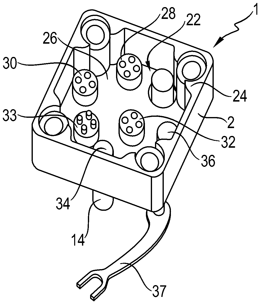
[0038] figure 2 The interior of the sensor device 1 is shown. ...


PUM


Abstract

The invention discloses a sensor arrangement for a hydraulic piston unit, in particular an axial piston machine, which has a plurality of sensors which are at least partially arranged together in a sensor housing. In this case, the sensors can be connected via a common plug.

Description

technical field [0001] The invention relates to a sensor device for a hydraulic ram unit. Background technique [0002] Hydraulic piston units have different operating states which can be characterized by process and state variables such as temperature, pressure, rotational speed of the drive shaft or the pressure medium volume flow of the piston unit. In order to obtain these variables, the plunger unit has a plurality of sensors, referred to as sensor devices. [0003] Laid-open document DE 10 2005 059 564 A1 shows a hydraulic plunger unit with a large number of discrete sensors which are arranged distributed on the plunger unit. In order to connect the individual sensors, an expensive cable harness is provided here, one cable harness being required for each sensor. [0004] The disadvantage of this solution is that the distributed sensors are susceptible to mechanical damage. Furthermore, the connection to the control unit via the cable harness is complex and, in the v...

Claims


Application Information

Patent Timeline
Patent Type & Authority Patents(China)
IPC IPC(8): F04B53/00
CPCG01D21/02G01D11/30G01D11/245
Inventor W.艾希纳B.许恩J.金特纳B.赛勒G.盖斯勒D.范阿尔斯特H-J.瓦格特J.基歇尔
Owner ROBERT BOSCH GMBH
Why Eureka
Try Eureka