Industrial robot clamping part

A technology for industrial robots and clamping components, applied in chucks, manipulators, manufacturing tools, etc., can solve the problems of falling items, insufficient friction of irregular items, etc., and achieve increased stability, wide application range, and stable clamping. Effect

Inactive Publication Date: 2018-05-15
GUANGXI RUIKE IND ROBOT CO LTD
View PDF5 Cites 29 Cited by
  • Summary
  • Abstract
  • Description
  • Claims
  • Application Information

AI Technical Summary

Benefits of technology

This patented technology improves upon existing methods by adding more or different types of floatation elements that allow it to move freely without getting stuck during use. These improvements include improved grip between an object being held together due to their own weight, increased contact area when they touch each other' surfaces, reduced slippage caused by unevenness over time, and enhanced stabilization against accidental movement. Additionally, there has been developed a mechanism called a lockable universal joint (LJ) where two parts work together tighten securely around small items like bolts.

Problems solved by technology

This technical problem addressed in this patented text relates to improving the stability of industrial robotics devices used during tasks such as assembly line production without causing damage on their surfaces themselves.

Method used


Image

  • Industrial robot clamping part
  • Industrial robot clamping part
  • Industrial robot clamping part

Examples


Embodiment 1

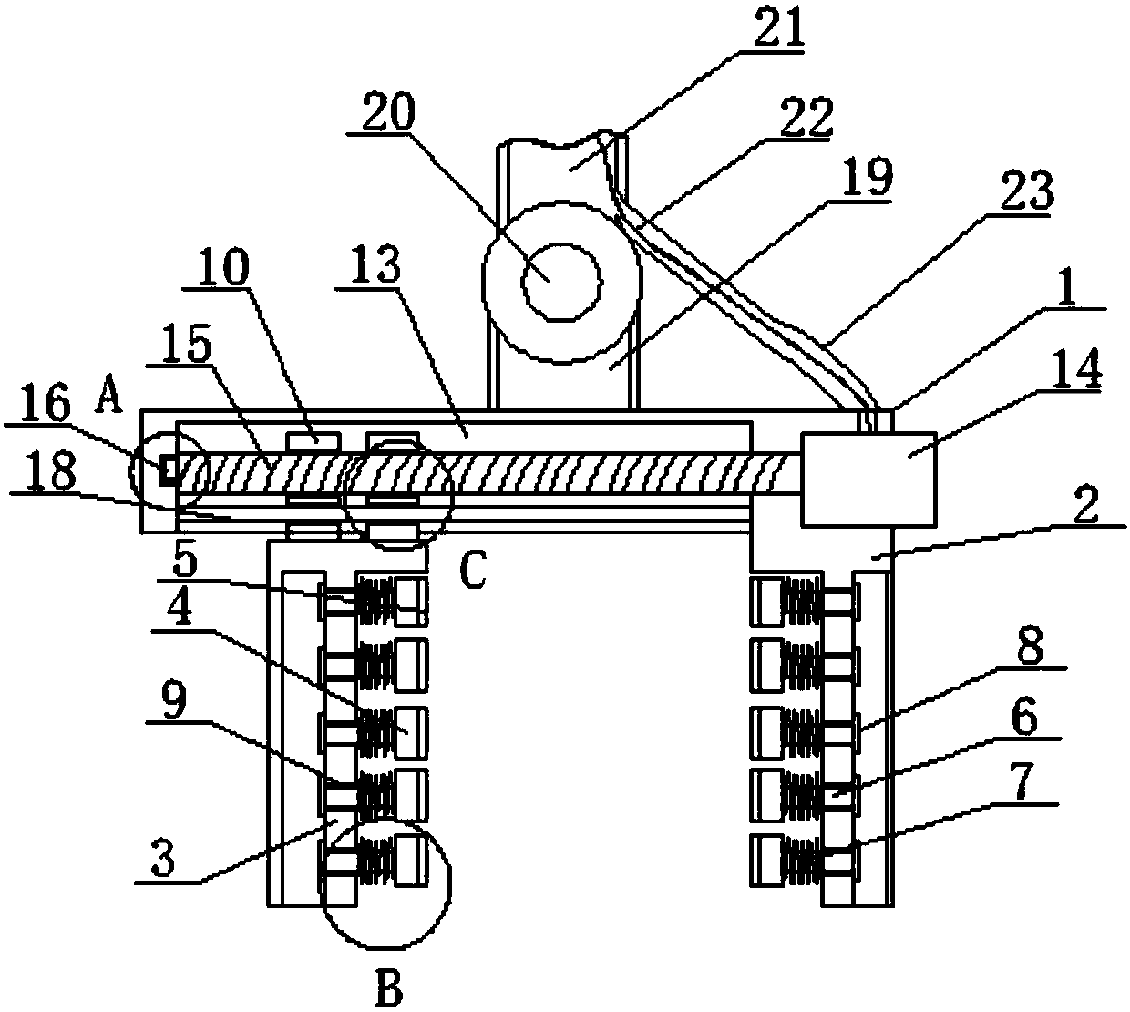
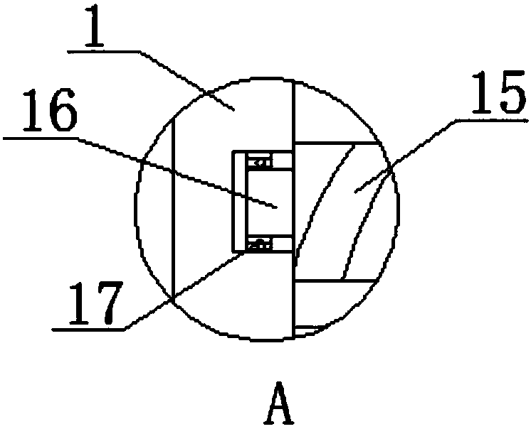
[0024] see Figure 1-Figure 5 As shown, a clamping part of an industrial robot includes a clamping beam 1, a fixed claw 2, a moving claw 3 and a connecting rod 19. One end of the clamping beam 1 is connected to the fixed claw 2, and the fixed claw 2 is matched with the movable claw 3. Items are grasped, and one end of the clamping beam 1 is connected to the moving claw 3, and the moving claw 3 can move freely in the horizontal direction to adapt to the grabbing of objects of different sizes. The moving claw 3 is provided with a plurality of through holes 9 for connecting multiple A floating block 4, a connecting rod 6 is arranged in the through hole 9, and the connecting rod 6 is used to connect the floating block 4 and cooperate with the limiting block 8 to limit the floating block 4, and one side of the floating block 4 is connected to the anti-slip block 5, and the anti-slip block 5 Increase the friction to make the clamping more stable. The connecting rod 6 is connected to...

Embodiment 2

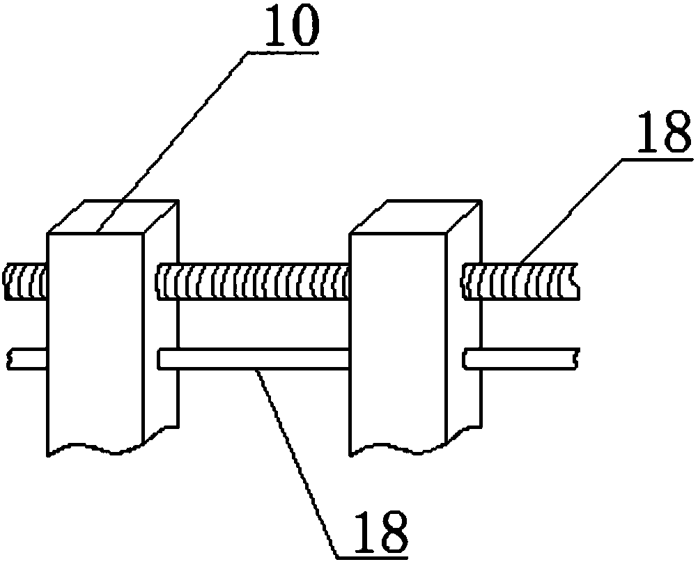
[0026] In addition, refer to Figure 1-Figure 5 , based on the above-mentioned embodiment, a plurality of through holes 9 are set on the movable claw 3, the fixed claw 2 and the movable claw 3 are set in the same way, and the fixed claw 2 and the movable claw 3 are symmetrically arranged, so that the fixed claw 2 and the movable claw 3 can be multiple The floating block 4 is set, and the clamp can bear the force symmetrically, and the clamped object is more stable. A matching anti-skid block 5 is set on one side of the floating block 4, and multiple floating blocks 4 are arranged on the same horizontal line, so that the floating block 4 can be evenly supported. force, the diameter of the limiting block 8 is greater than the diameter of the through hole 9, the connecting rod 6 is flexibly connected to the through hole 9, so that the limiting block 8 will not fall off, the connecting rod 6 can move freely, and the sliding block 10 is symmetrically arranged on the moving claw 3 ,...


PUM


Abstract

The invention discloses an industrial robot clamping part. The industrial robot clamping part comprises a clamping beam, a fixing claw, moving claws, floating blocks, antiskid blocks, linking rods, springs, limiting blocks, through holes, slide blocks, threaded holes, smooth holes, a slide groove, an automatic locking motor, screw, a rolling shaft, a bearing, a slide rod, a connecting rod, a universal shaft, a mechanical arm, a connecting line and a protecting cover. Multiple uniformly distributed floating blocks are arranged on the fixing claw and the moving claws and provide elastic force through the springs, when irregular objects are clamped, the floating blocks can be automatically adjusted according to the surface change of the irregular objects to adapt to irregular surfaces, the slide block is provided with the threaded hole and the smooth hole, the threaded holes and the smooth holes are connected with the screw and the slide rod respectively, the moving claws are prevented from wobbling, the screws are connected with the automatic locking motor, after clamping, the automatic locking motor can be automatically locked, the moving claws are limited, the connecting rod is provided with the universal shaft, the clamp can freely rotate in the certain direction, and clamping can be conducted by many angles.

Description


Claims


Application Information

Patent Timeline
Owner GUANGXI RUIKE IND ROBOT CO LTD
Why Eureka
Try Eureka