Filling nozzle of liquid filling machine

A filling machine and filling nozzle technology, applied in packaging and other directions, can solve the problems of dirty packaging, difficult packaging, liquid splashing, etc., and achieve the effect of avoiding dripping

Active Publication Date: 2018-05-15
湖北永进药业股份有限公司
View PDF6 Cites 1 Cited by
  • Summary
  • Abstract
  • Description
  • Claims
  • Application Information

AI Technical Summary

Problems solved by technology

As far as the liquid filling machine is concerned, when filling, the filling nozzle of the filling machine is docked with the mouth tube on the package and the liquid is poured into the package. The filling nozzle quickly releases the liquid, causing the liquid to splash and pollute the package. At the mouth of the tube, the packaging is not easy to seal
After the filling is completed, because the filling pipeline has a certain length, when the control valve is closed, the material in the filling pipeline will still enter the package under the action of gravity, making it difficult to accurately control the weight of the package
At the same time, the excess material in the filling pipeline may also drip on the packaging, making the packaging dirty, and the liquid falling on the mouth tube of the packaging may also affect the sealing of the packaging, causing the phenomenon of lax sealing, thus causing the packaging to be damaged. Leakage

Method used


Image

  • Filling nozzle of liquid filling machine
  • Filling nozzle of liquid filling machine
  • Filling nozzle of liquid filling machine

Examples


Embodiment 1

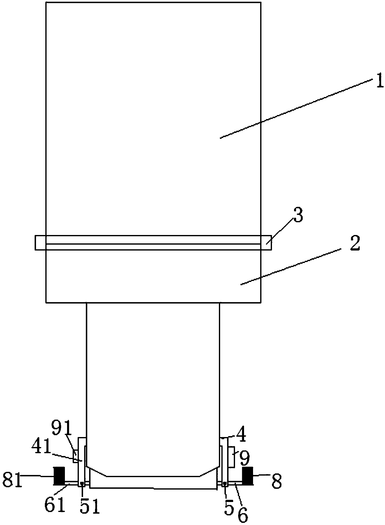
[0029] Such as figure 1 , figure 2 As shown, a filling mouth of a liquid filling machine includes a filling mouth end 1 and a filling head 2, the filling mouth end 1 is connected to the filling head 2, and the filling head 2 The outer wall is provided with a first bracket device 41 and a second bracket device 4, the first bracket device 41 is connected to the first wheel shaft 51, and the first wheel shaft 51 is connected to a rotatable first balance bar 61, so Both ends of the first balance bar 61 are respectively connected with a first baffle plate 71 and a first iron block 81; the second support device 4 is connected with the second wheel shaft 5, and the second wheel shaft 5 is connected with a The second balance pole 6, the two ends of the second balance pole 6 are respectively connected with the second baffle plate 7 and the second iron block 8, the first baffle plate 71 and the second baffle plate 7 are located in the tank Bottom of the head.

[0030] When the filli...

Embodiment 2

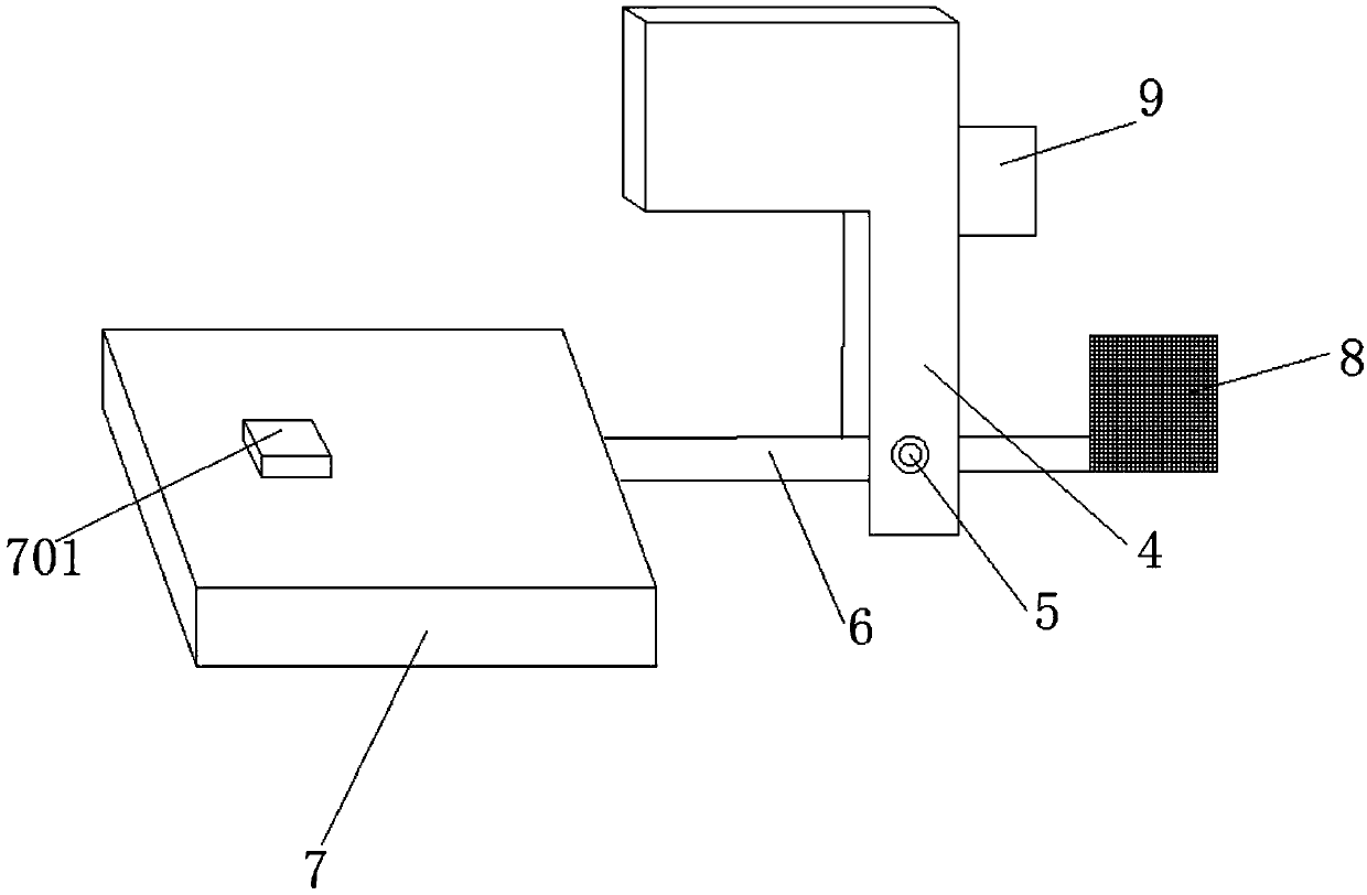
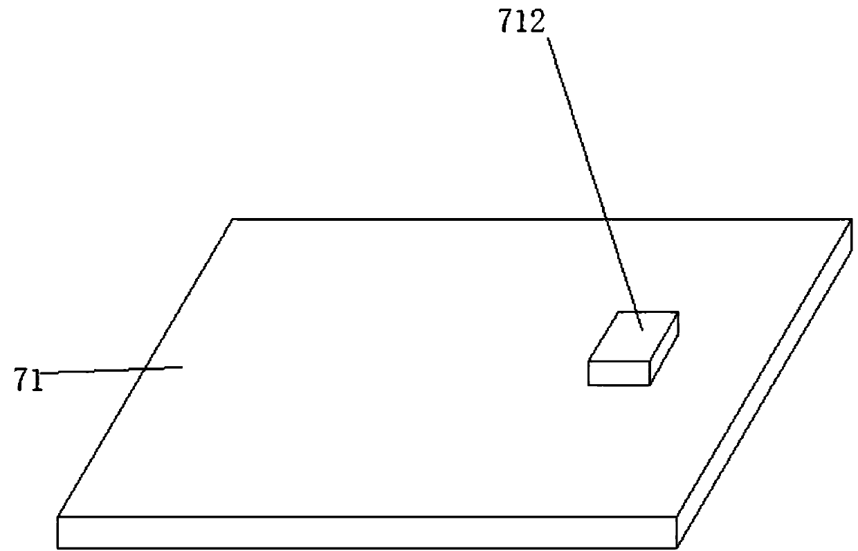
[0032] Based on Example 1, image 3 , Figure 4 As shown, the upper surface of the first baffle 71 is provided with a first protrusion 712, and the lower surface of the first baffle 71 is provided with a first groove 711; the upper surface of the second baffle 7 is provided with a The second protrusion 701 matched with the size of the first groove 711, the lower surface of the second baffle plate 7 is provided with a second groove matched with the size of the first protrusion 712;

[0033]When the filling is completed, the force exerted by the liquid on the first baffle 71 is smaller than the force exerted by the first iron block 81 on the first balance bar 61, so that the first baffle 71 moves toward the bottom of the filling head 2, and similarly The second baffle 7 also moves towards the bottom of the filling head 2 , so that the first baffle 71 and the second baffle 7 return to the bottom of the filling head 2 . Since the upper surface of the first baffle plate 71 is pro...

Embodiment 3

[0035] Based on Example 1, such as figure 1 , figure 2 As shown, the first support device 41 is provided with a first support rod, the other end of the first support rod is in contact with the first baffle 71, and the second support device 4 is provided with a second support rod 10 , the other end of the second support rod 10 is in contact with the second baffle plate 7 . Since the first support device 41 is provided with a first support rod, and the other end of the first support rod is in contact with the first baffle plate 71, when the first baffle plate 71 moves to the bottom of the filling head 2, the first support rod prevents the The movement of the first baffle 71 is ensured, so that the first baffle 71 is fixed at the bottom of the filling head. Similarly, the movement of the second baffle 7 is also prevented by the second support rod 10, so that the second baffle 7 is also fixed. At the bottom of filling head 2.


PUM


Abstract

The invention discloses a filling nozzle of a liquid filling machine. The filling nozzle comprises a filling nozzle end and a filling head which are connected. A first support device and a second support device are arranged on the outer wall of the filling head. The first support device is connected with a first axle which is connected with a rotatable first balancing rod. The two ends of the first balancing rod are connected with a first baffle and a first iron block respectively. The second support device is connected with a second axle which is connected with a rotatable second balancing rod. The two ends of the second balancing rod are connected with a second baffle and a second iron block respectively. The first baffle and the second baffle are located at the bottom of the filling head. By means of the filling nozzle, it can be avoided that rapid-outflow liquid is splashed out of a packaging object when a packaging object opening pipe is filled with the liquid, and meanwhile the liquid dropping phenomenon can be avoided.

Description

technical field [0001] The invention relates to the technical field of liquid filling, in particular to a canning mouth of a liquid filling machine. Background technique [0002] Filling equipment is mainly a type of product in packaging machines. From the perspective of packaging materials, it can be divided into liquid filling machines, paste filling machines, powder filling machines, and particle filling machines. As far as the liquid filling machine is concerned, when filling, the filling nozzle of the filling machine is docked with the mouth tube on the package and the liquid is poured into the package. The filling nozzle quickly releases the liquid, causing the liquid to splash and pollute the package. At the mouth tube, the packaging is not easy to seal. After the filling is completed, because the filling pipeline has a certain length, when the control valve is closed, the material in the filling pipeline will still enter the package under the action of gravity, maki...

Claims


Application Information

Patent Timeline
Patent Type & Authority Applications(China)
IPC IPC(8): B65B39/00B65B59/00
CPCB65B39/00B65B59/00
Inventor 周绍明石昭良
Owner 湖北永进药业股份有限公司
Why Eureka
Try Eureka