Optical light distribution module and bulb lamp structure with optical light distribution module

A technology of light distribution module and bulb lamp, which is applied to semiconductor devices of light-emitting elements, light source, light source fixation, etc. Good luminous efficiency

Pending Publication Date: 2018-05-15
PUTIAN INTELLIGENT LIGHTING INST
View PDF0 Cites 1 Cited by
  • Summary
  • Abstract
  • Description
  • Claims
  • Application Information

AI Technical Summary

Problems solved by technology

However, the use of diffusive polycarbonate (PC) material as the lampshade shell will cause the loss of light emitted by the LED light source particles to be more than 9%. The light loss will exceed 9% again, making the utilization efficiency of light energy greatly reduced
If a lens is used to control the light output, due to the dispersion effect of the lens on the light, the light will be unevenly distributed in space.

Method used


Image

  • Optical light distribution module and bulb lamp structure with optical light distribution module
  • Optical light distribution module and bulb lamp structure with optical light distribution module
  • Optical light distribution module and bulb lamp structure with optical light distribution module

Examples


Embodiment 1

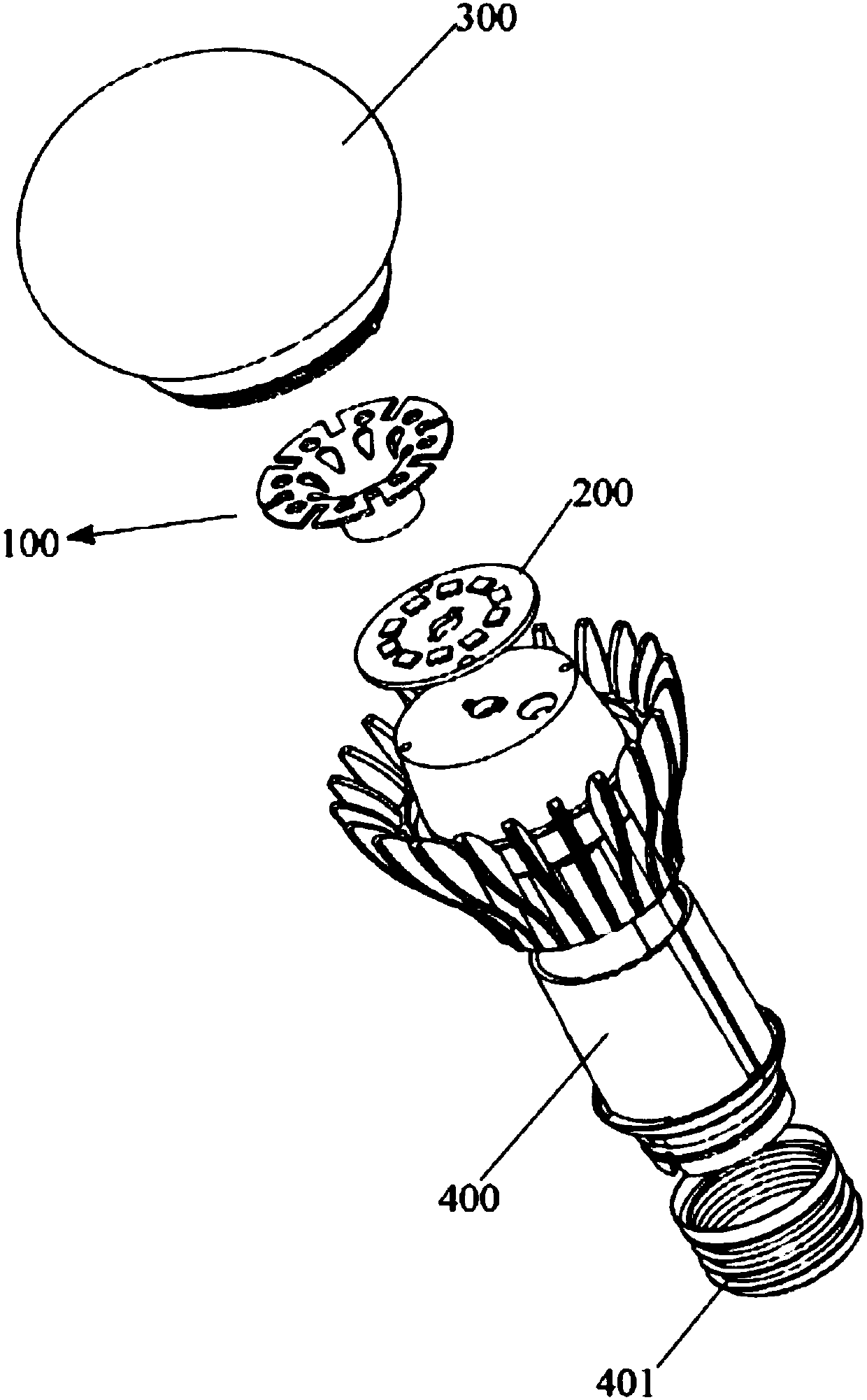
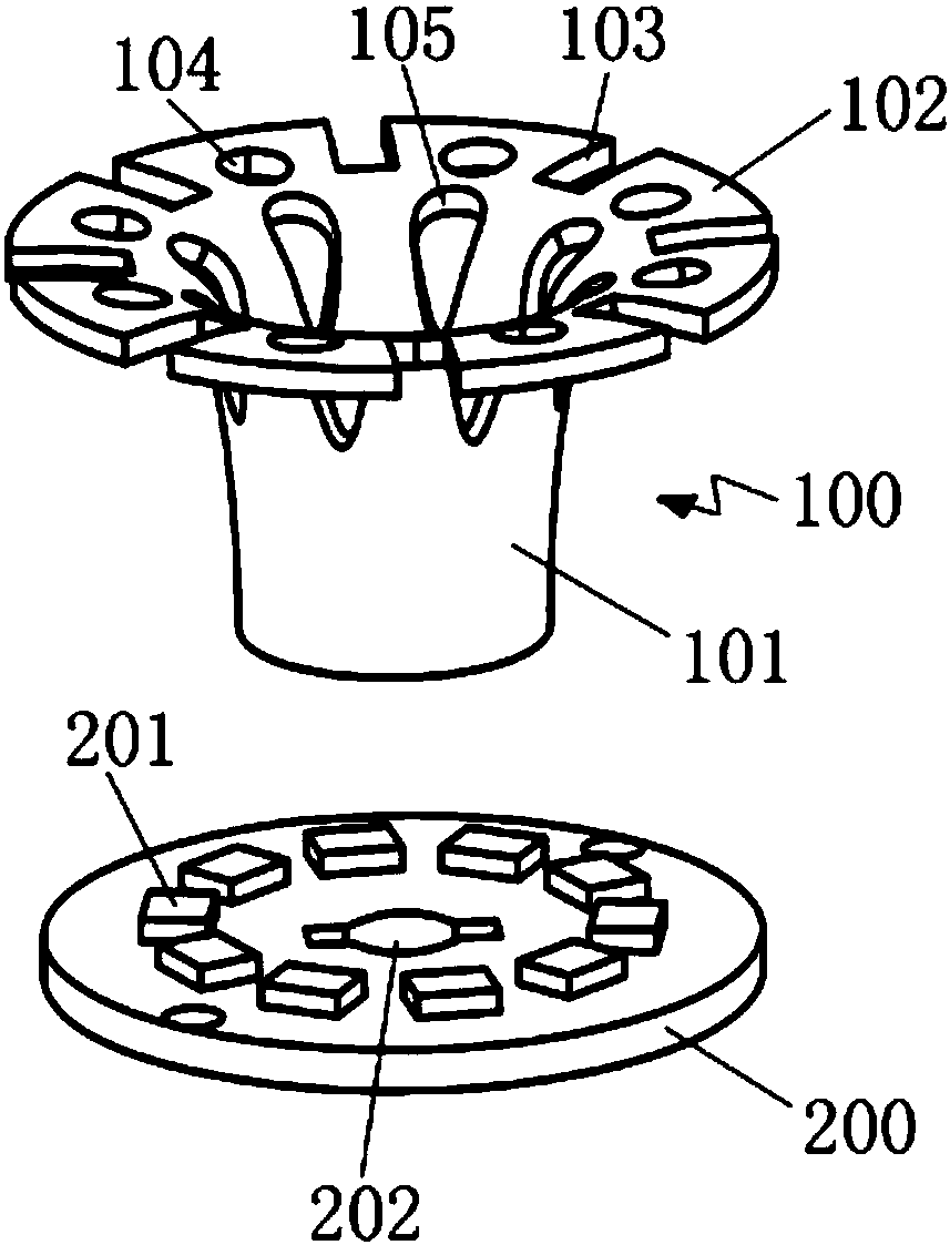
[0031] exist figure 2 In one embodiment shown, this optical light distribution module 100 may include: a light-transmitting device configured to transmit light emitted from an LED light source on its back side according to an optical path setting configuration; The reflective device of the light device is configured to block and reflect the light emitted from the LED light source.

[0032] In order to achieve a better light output effect with a larger angle, the optical light distribution module is configured to transmit a certain proportion of light in the direction of the outgoing light of an LED light source 201, and block a certain proportion of light in the direction of the outgoing light. It is emitted at a reverse angle, and a certain proportion of the light will be emitted at a certain angle under the joint action of transmission and reflection to enhance the light output effect.

[0033] Specifically, in a preferred example, the above-mentioned light-reflecting devi...

Embodiment 2

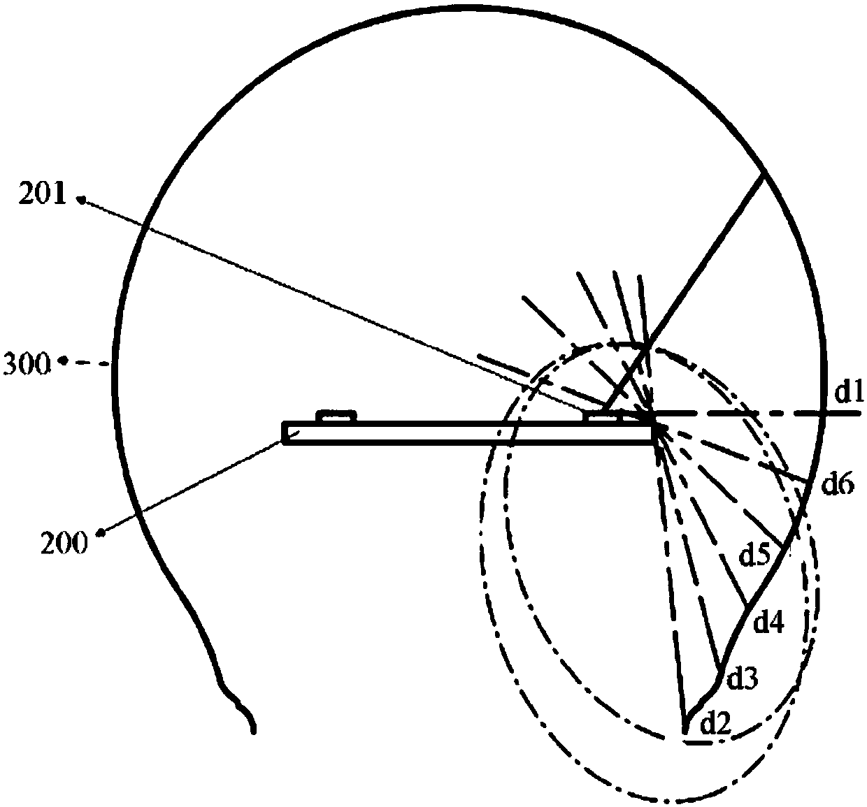
[0049] exist Figures 6 to 10 In another embodiment shown, different configurations of optical light distribution modules with such functionality are provided. according to Figure 5 and 6 As shown, the optical light distribution module 300 may include a light-transmitting device configured to transmit the light emitted by the LED light source 201 from its backside; and a light-reflecting device 303 arranged in the structure of the light-transmitting device configured to reflect At least a portion of the light emitted from the LED light source.

[0050] For example, Figure 6 and 7 There may be different configurations of light-transmitting means. exist Figure 7 In the example shown, only the light-transmitting device 301 may be provided. The light-transmitting device 301 may have a substantially cylindrical configuration with a hollow center (in some implementations, it may not be a hollow configuration). This type of configuration is used to completely cover the LED...


PUM


Abstract

The invention provides an optical light distribution module. The optical light distribution module comprises a light transmission device which is configured to transmit the light emitted by an LED light source from the back side of the light transmission device and a reflecting device which is coupled to the light transmission device and configured to block and reflect the light from the LED lightsource. A bulb lamp structure which is designed based on the above module comprises the LED light source which is arranged in an annular configuration and the above optical light distribution modulewhich is fixed on a lightening face of the LED light source. The module has the beneficial effects that a bulb lamp which uses the optical light distribution module is better in lightening efficiencyand capable of configuring a uniform, effective and centralized exit light path and avoiding the light loss; the optical light distribution module is applicable to the bulb lamps of any size and any power.

Description

technical field [0001] The invention mainly relates to a bulb lamp and an optical light distribution module for adjusting light output thereof. Background technique [0002] According to the Energy Star standard, the relevant requirements for light distribution of bulb lamps are: lamps should have uniform light intensity distribution within the space range of 0 to 135 degrees (vertically symmetrical). The difference in light intensity between any angles does not exceed 20%, and there is at least 5% of the total lumens of light intensity in the range of 135 to 180 degrees. The measurement of vertical symmetry should be in 3 intervals, which are 0, 45 and 90 degrees. [0003] The LED particles currently on the market basically emit light from one side, that is, a single-side light source. In order to have uniform light illumination in the space range of 135 to 180 degrees, it is necessary to perform secondary optical light distribution on the outgoing light in the space rang...

Claims


Application Information

Patent Timeline
Patent Type & Authority Applications(China)
IPC IPC(8): F21K9/232F21K9/65F21V7/00F21V19/00F21V17/16F21Y115/10
CPCF21K9/232F21K9/65F21V7/00F21V17/164F21V19/001F21Y2115/10
Inventor 徐鹤还
Owner PUTIAN INTELLIGENT LIGHTING INST
Why Eureka
Try Eureka