
Bending machine for processing tube joints

A technology for bending machines and pipe sections, applied in the field of bending machines, can solve the problems of long time-consuming joints of pipe sections and the inability to guarantee full sealing at the joints, and achieve the effects of reducing manpower and material resources, enhancing brightness and simple operation.

Inactive Publication Date: 2018-05-18
江苏威科变压器有限公司
View PDF0 Cites 0 Cited by
  • Summary
  • Abstract
  • Description
  • Claims
  • Application Information

AI Technical Summary

Problems solved by technology

[0003] The technical problem to be solved by the present invention is to overcome the long time-consuming process of standard formed pipe joints, and the joints of pipe joints cannot be fully sealed, and provide a folding joint that is simple to operate, easy to use, saves manpower and material resources, and improves work efficiency. Bending machine, this device can make standard flange joints, so that the connection between the pipe sections and pipe sections is connected in the form of low-pressure flanges. Manpower and material resources improve work efficiency. At the same time, the arc-shaped plate is used to prevent the pipe section from being crushed and causing fragments to pop out and injure the operator. The light bulb device can enhance the brightness of the processing environment and make it easier for the operator to see the processing details.

Method used


Image

  • Bending machine for processing tube joints

Examples


Embodiment 1

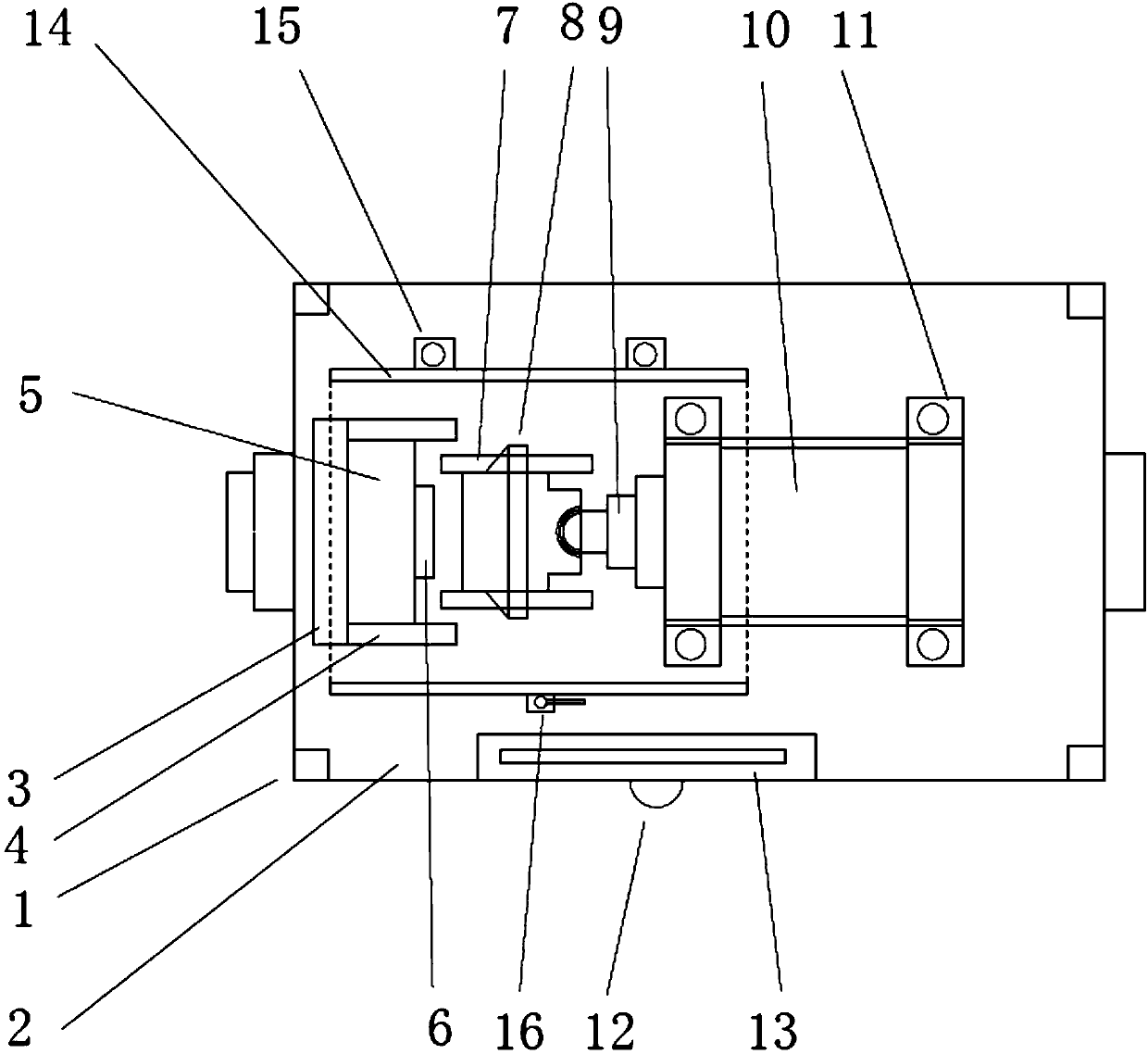
[0015] Such as figure 1 As shown, the present invention provides a bending machine for processing pipe joints, including a support rod 1, a base 2 is provided on the upper part of the support rod 1, a baffle 3 is provided on one side of the upper surface of the base 2, and a baffle 3 is provided at both ends. There are laterally placed side plates 4, clamping blocks 5 are arranged between the two side plates 4, and the right side of the clamping block 5 is provided with an annular belt 6. The right side of the annular belt 6 is provided with two transverse guide rails 7 placed front and rear, A briquetting block 8 is arranged between the two transverse guide rails 7, a push block 9 is provided on the right side of the briquetting block 8, an oil cylinder 10 is provided on the right side of the push block 9, an oil cylinder base 11 is provided at the bottom of the oil cylinder 10, and a lamp holder 12 is connected to the side of the base 2, A light bulb 13 is provided on the to...


PUM


Abstract

The invention discloses a bending machine for processing tube joints. The bending machine comprises a support rod, and a base is arranged at the upper part of the support rod. A baffle plate is arranged on one side of the upper surface of the base, side plates are transversely arranged at the two ends of the baffle plate, and a clamping block is arranged between the two side plates. A ring belt isarranged on the right side of the clamping block, and two transverse guide rails are arranged on the right side of the ring belt in a mode of fore and after placement. A pressing block is arranged between the two transverse guide rails, and a push block is arranged on the right side of the pressing block. An oil cylinder is arranged on the right side of the push block, and an oil cylinder base isarranged at the bottom of the oil cylinder. The side face of the base is connected with a lamp bracket, and a bulb is arranged at the upper part of the lamp bracket. An arc-shaped plate is arranged at the upper part of the push block, a fixed base is arranged on one side of the arc-shaped plate, and a fixed valve is arranged on the other side of the arc-shaped plate. The bending machine is used for processing the tube joints, has the advantages of simple operation and convenience in use, saves human and material resources, and improves the working efficiency.

Description

technical field [0001] The invention relates to a bending machine, in particular to a bending machine for processing pipe joints, and belongs to the technical field of bending machines. Background technique [0002] In production-oriented enterprises, the connection between pipe sections is made by manual welding, and joints are needed to connect the two, and it takes about 5 hours to make a standard formed joint, and the joints of pipe sections cannot be guaranteed Full sealing requires a lot of manpower and material resources, and also wastes a lot of time, greatly reducing work efficiency. At the same time, some pipe sections may be crushed during processing. Contents of the invention [0003] The technical problem to be solved by the present invention is to overcome the long time-consuming process of standard formed pipe joints, and the joints of pipe joints cannot be fully sealed, and provide a folding joint that is simple to operate, easy to use, saves manpower and ...

Claims


Application Information

Patent Timeline
Patent Type & Authority Applications(China)
IPC IPC(8): B21D7/16B21D7/06
CPCB21D7/16B21D7/06
Inventor 郭福斌
Owner 江苏威科变压器有限公司
Learn More