Chemical vapor deposition device and application method thereof

A technology of chemical vapor deposition and loading position, which is applied in the direction of gaseous chemical plating, metal material coating process, coating, etc., can solve the problems of poor film performance and achieve the effect of improving performance

Inactive Publication Date: 2018-05-18
HUAIAN IMAGING DEVICE MFGR CORP
View PDF6 Cites 1 Cited by
  • Summary
  • Abstract
  • Description
  • Claims
  • Application Information

AI Technical Summary

Problems solved by technology

[0003] However, the performance of thin films prepared using existing chemical vapor deposition equipment is poor

Method used


Image

  • Chemical vapor deposition device and application method thereof
  • Chemical vapor deposition device and application method thereof
  • Chemical vapor deposition device and application method thereof

Examples


Embodiment Construction

[0026] As mentioned in the background, thin films formed using prior art vapor deposition devices have poor performance.

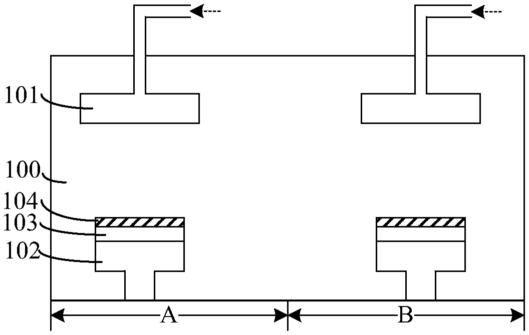
[0027] figure 1 It is a structural schematic diagram of a chemical vapor deposition device.

[0028] Please refer to figure 1 , a reaction chamber 100, the reaction chamber 100 includes a first zone A and a second zone B; a first chemical vapor deposition part located in the first zone A reaction chamber 100, the first chemical vapor deposition part includes: a first chemical vapor deposition part located in the first zone A There is a first shower assembly 101 on the top of the first zone A reaction chamber 100; a first heater 102 arranged at the bottom of the reaction chamber 100 opposite to the first shower assembly 101; a first chip 103 located on the surface of the first heater 102 , the surface of the first chip 103 is opposite to the surface of the first shower assembly 101; the second chemical vapor deposition part located in the reaction chamber...


PUM


Abstract

The invention discloses a chemical vapor deposition device and an application method thereof. The chemical vapor deposition device comprises a reaction cavity, a spraying module penetrating into the reaction cavity from the top of the reaction cavity, and a base positioned on at least one side of the spraying module; the base comprises a loading surface, and has a working position state; and whenthe base is located in the working position state, the loading surface is perpendicular to a horizontal plane, and is towards the side wall of the spraying module. Films formed on the surfaces of chips by using the chemical vapor deposition device are better in performance.

Description

technical field [0001] The invention relates to the technical field of chemical vapor deposition, in particular to a chemical vapor deposition device and an application method thereof. Background technique [0002] Chemical vapor deposition (Chemical vapor deposition, CVD) is a process technology in which reactants react chemically under gaseous conditions to form solid substances that are deposited on the surface of a heated solid substrate to obtain solid materials. It is realized by chemical vapor deposition devices. Specifically, the chemical vapor deposition device passes the reaction gas into the reaction chamber through the gas inlet device, and controls the reaction conditions such as pressure and temperature in the reaction chamber, so that the reaction gas reacts, thereby completing the deposition process steps. [0003] However, the performance of thin films prepared using existing chemical vapor deposition equipment is poor. Contents of the invention [0004] ...

Claims


Application Information

Patent Timeline
Patent Type & Authority Applications(China)
IPC IPC(8): C23C16/455C23C16/458
CPCC23C16/4588C23C16/45565C23C16/4557
Inventor 常传栋吴孝哲林宗贤吴龙江薛超
Owner HUAIAN IMAGING DEVICE MFGR CORP
Why Eureka
Try Eureka