Spraying device for coloring clothes
A technology of spraying device and clothing, which is applied in the direction of processing textile material equipment configuration, spraying/spraying textile material processing, etc., can solve the problem of not being able to spray in all directions.
- Summary
- Abstract
- Description
- Claims
- Application Information
AI Technical Summary
Problems solved by technology
Method used
Image

Examples
specific Embodiment approach 1
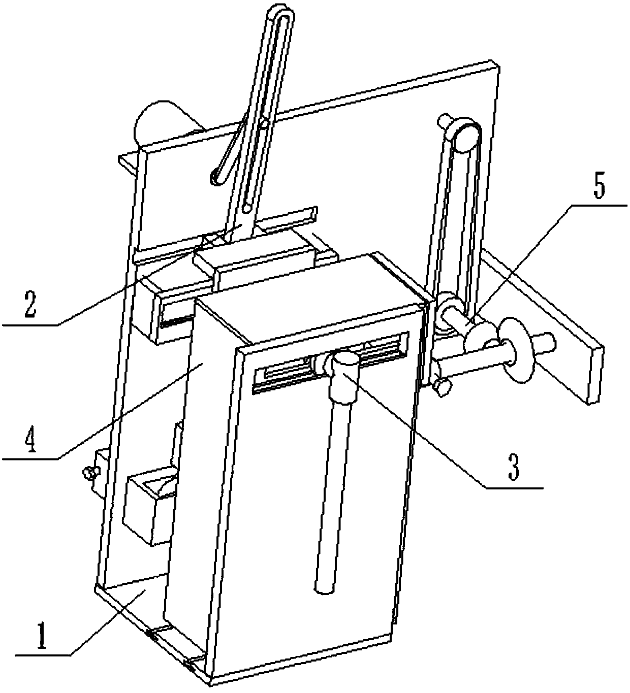
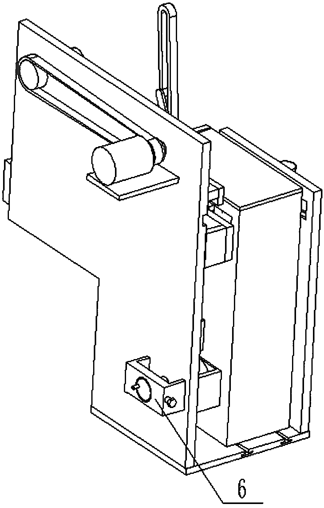
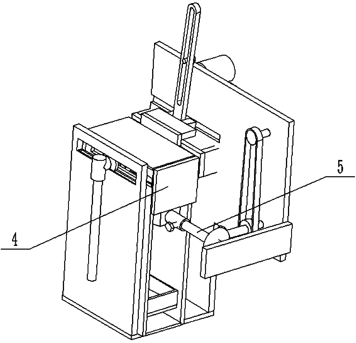
[0026] Such as Figure 1 to Figure 10 As shown, a spraying device for clothing coloring includes a base 1, a drive control device 2, a rotating spraying structure 3, a recovery baffle structure 4, a clothing fixed rotating structure 5 and a protection device 6, and the drive control The device 2 is fixedly connected to the upper base 1, the rotating spraying structure 3 is connected to the drive control device 2 through gears, the rotating spraying structure 3 is rotatably connected to the base 1, the recovery baffle structure 4 is slidably connected to the base 1, and the clothing is fixed to rotate The structure 5 is connected to the drive control device 2 through a belt, the clothing fixed and rotating structure 5 is rotatably connected to the base 1 , and the protection device 6 is fixedly connected to the base 1 . By driving the control device 2, the rotating spraying structure 3 is swung and rotated for spraying, and at the same time, the displacement stroke of the rotat...
specific Embodiment approach 2
[0027] Such as Figure 1 to Figure 10 As shown, this embodiment will further describe Embodiment 1. The base 1 includes a bottom plate 1-1, a left plate 1-2, a right plate 1-3, a front plate 1-4, and a swinging lateral slide groove 1-5. , right through slot 1-6, motor shaft through hole 1-7, adjustment shaft through hole 1-8, driven shaft through hole 1-9 and platform chute 1-10, left plate 1-2 and right plate 1- 3 are respectively fixedly connected to the left and right ends of the base plate 1-1, the front plate 1-4 is fixedly connected to the front end of the left plate 1-2, the swing horizontal chute 1-5, the motor shaft through hole 1-7, the adjustment shaft through hole 1-8 and the driven shaft through hole 1-9 are all arranged on the left plate 1-2, the right through groove 1-6 is arranged on the right plate 1-3, and the platform chute 1-10 is provided with two, two The platform chute 1-10 is all arranged on the bottom plate 1-1.
specific Embodiment approach 3
[0028] Such as Figure 1 to Figure 10As shown, the second embodiment is further described in this embodiment. The drive control device 2 includes a motor 2-1, a rotating rod 2-2, a driving cylinder 2-3, a driving rod 2-4, and a sliding block 2-5. , driving slide 2-6, transmission rack 2-7, hinged displacement block 2-8, fixed adjustment block 2-9, rectangular slot 2-10, displacement rack 2-11, adjustment gear 2-12, adjustment shaft 2-13. Rotate the disc 2-14 and the hand-rotated cylinder 2-15, the motor 2-1 is fixedly connected to the left plate 1-2, and the drive shaft of the motor 2-1 is connected to the motor shaft through hole 1-7 in rotation , the rotating rod 2-2 is fixedly connected to the transmission shaft of the motor 2-1, the driving cylinder 2-3 is fixedly connected to the rotating rod 2-2, the driving rod 2-4 is provided with a driving groove, and the driving cylinder 2-3 slides Connected in the drive groove of the drive rod 2-4, the lower end of the drive rod 2-...
PUM
 Abstract
Description
Claims
Application Information
 - R&D
- Intellectual Property
- Life Sciences
- Materials
- Tech Scout
- Unparalleled Data Quality
- Higher Quality Content
- 60% Fewer Hallucinations
Browse by: Latest US Patents, China's latest patents, Technical Efficacy Thesaurus, Application Domain, Technology Topic, Popular Technical Reports.
© 2025 PatSnap. All rights reserved.Legal|Privacy policy|Modern Slavery Act Transparency Statement|Sitemap|About US| Contact US: help@patsnap.com