
Detector of rebound apparatus

A technology of a rebound hammer and a fixed guide rail is applied in the field of the testing device of the hammer, which can solve the problems of inconvenient use, distorted testing data of the calibrator, and inability to test multiple indicators at the same time, so as to achieve convenient operation, improve detection accuracy, The effect of easy firing and position control

Pending Publication Date: 2018-05-18
舟山市博远科技开发有限公司
View PDF0 Cites 3 Cited by
  • Summary
  • Abstract
  • Description
  • Claims
  • Application Information

AI Technical Summary

Problems solved by technology

At present, there is a single device at home and abroad that cannot test multiple indicators at the same time, and it is inconvenient to use at the same time, and some testers will produce the phenomenon of detection data distortion

Method used


Image

  • Detector of rebound apparatus
  • Detector of rebound apparatus
  • Detector of rebound apparatus

Examples


Embodiment 1

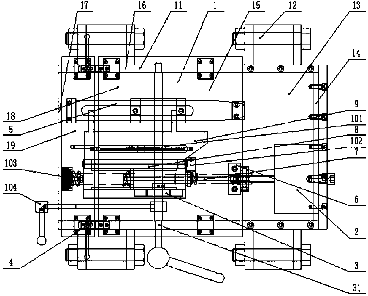
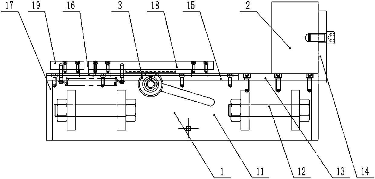
[0064] A tester for a rebound instrument, comprising: a base part 1 including side plates 11 on both sides and a rear cover 17, the upper right side of the base part 1 is fixed with a steel anvil base 13, and the steel anvil 2 passes through the back stop of the steel anvil Plate 14 is installed on described steel anvil base 13 (referring to Figure 1-2 );

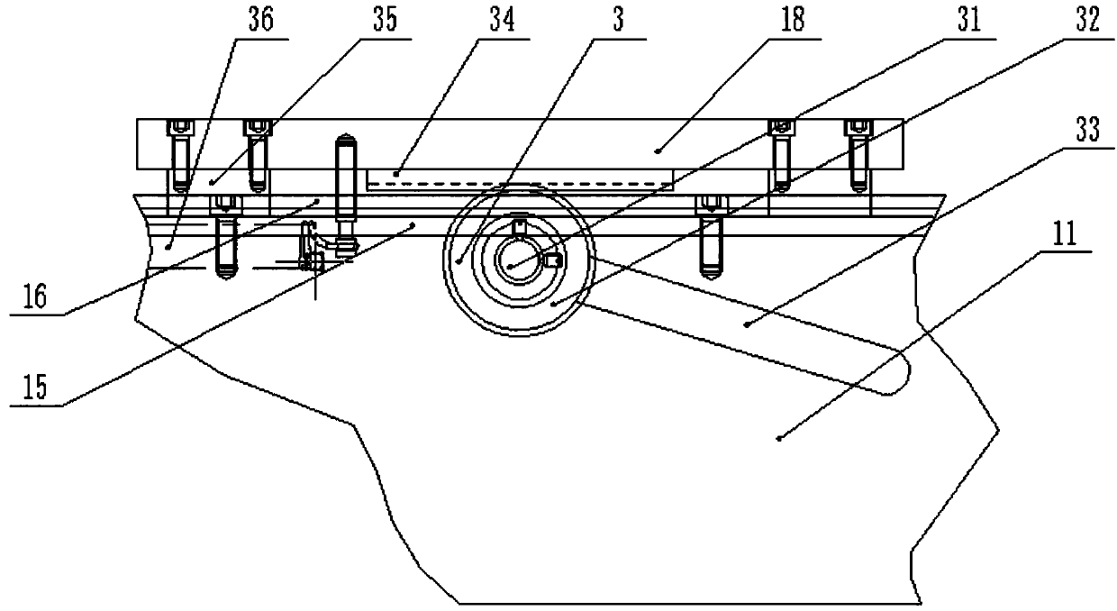
[0065] The top of the side plate 11 is installed with a slideway 16 through bolts, and the two sides of the bottom plate 15 are installed with a slide block 35 through bolts. Realize the translation motion pair; (see figure 2 ), two handles 12 are installed on the side panels 11 on both sides.

[0066] The main sliding plate 18 and the auxiliary sliding plate 19 are slidably connected with the slideway 16 through the slider 35, the main sliding plate 18 is located on the right side of the auxiliary sliding plate 19, and the main sliding plate 18 and the auxiliary sliding plate 19 pass through the fixed guide rail parts ...

Embodiment 2

[0074] Embodiment 2: The structure is the same as that of Embodiment 1, and the support sleeve 105 is added to be installed between the rear pull baffle 103 and the movement part 7 . The support cover 105 includes a support cover base 1051 embedded in the rear pull baffle 103, a support cover positioning part 1053 fixed to the guide bar 82 and an internal support cover through hole 1052 (see Figure 23-24 ), the effect of increasing the support sleeve 105 is: when the length of the return spring is longer, the support sleeve 105 is fixed between the rear pull baffle plate 103 and the guide bar 82, and the return spring moves in the support sleeve through hole 1052 to prevent the return spring from Jump out during compression.

[0075] The calibrator completes multiple detection indexes of the rebound hammer in one device, which is convenient for operators to operate and improves work efficiency at the same time. The main slide plate and the auxiliary slide plate are connected...


PUM


Abstract

The invention discloses a detector of a rebound apparatus, which comprises a main gliding plate and a secondary gliding plate, and a static steel anvil; the main gliding plate and the secondary gliding plate are moveably installed on a base, and can mutually move through a fastening spring, and lock through a fixing lead rail part; the upper parts of the main gliding plate and the secondary gliding plate are equipped with a shell fixing part and a flange guide part; a core part to be detected is installed in the flange guide part. The front and back parts of the core part are fixed through a buckle part and a back pull baffle; when technical parameters of the rebound apparatus are detected, the index component rod, and other precisions of the shell body are detected through static state; the elastic rod collides to the center of the steel anvil through the effect of the elastic hammer of the core on the elastic rod, the counteractive force of the elastic hammer is acted on a pointer component, thus the pointer component is moved with a certain distance, and precision of the core part is detected. Through a single device, the detector can detect many parameters of the rebound apparatus; the identifying precision is high and the design structure is reasonable, and the detector has extremely high performance cost.

Description

technical field [0001] The invention relates to a detection device for a rebound hammer used in the construction field, in particular to a tester for a rebound hammer. Background technique [0002] At present, domestic and foreign construction fields generally use rebound hammers to identify the strength of concrete structures. After leaving the factory or using a rebound hammer for a period of time, it is necessary to verify its accuracy. The contents of the verification include many items, such as for the standard The fixed value of the rebound rate of the steel anvil, the positioning accuracy of the "100" scale line of the scale on the upper shell of the rebound hammer, and the working length of the spring of the spring before stretching and firing, and the spring of the spring after stretching to firing. The impact length of the bouncing hammer, the take-off position of the bouncing hammer and other indicators at the position. This requires a standard rebound tester to ...

Claims


Application Information

Patent Timeline
Patent Type & Authority Applications(China)
IPC IPC(8): G01N3/52
CPCG01N3/52
Inventor 应纪伟周岳年李丹严嘉杰李健力
Owner 舟山市博远科技开发有限公司
Learn More