Sink type cleaning device

A cleaning device, sink-type technology, applied in cleaning devices, household cleaning devices, cleaning equipment, etc., can solve problems such as impact, damage, and increase the efficiency of pressure water pumps

Pending Publication Date: 2018-05-22
NINGBO FOTILE KITCHEN WARE CO LTD
View PDF5 Cites 2 Cited by
  • Summary
  • Abstract
  • Description
  • Claims
  • Application Information

AI Technical Summary

Problems solved by technology

However, this ventilating device will cause hot and humid gas to be discharged into the cabinet, causing dampness, mold, and damage to the cabinet.
In this regard, the applicant's application number is 201610625850.X's Chinese patent discloses a ventilating device for a sink type washing machine, including a first sink, a second sink with a built-in cleaning mechanism, and a ventilating structure. The exhaust assembly on the side wall of the second water tank, the air intake assembly arranged on the side wall of the first water tank, and the ventilation pipe connected between the exhaust assembly and the air intake assembly, the exhaust assembly is in fluid communication with the second water tank , the air intake component is in fluid communication with the first water tank, it can maintain the balance of internal and external air pressure to protect the sink type cleaning device of the cabinet, but because the air intake component still cannot achieve the effect of rapidly condensing steam, the steam is easy to backlog, so as to increase the second water tank The pressure inside the tank will affect the efficiency of the water pump. At the same time, the water vapor will easily condense on the edge of the intake assembly to form water droplets and flow out of the washing machine.

Method used


Image

  • Sink type cleaning device
  • Sink type cleaning device
  • Sink type cleaning device

Examples


Embodiment Construction

[0022] The present invention will be further described in detail below in conjunction with the accompanying drawings and embodiments.

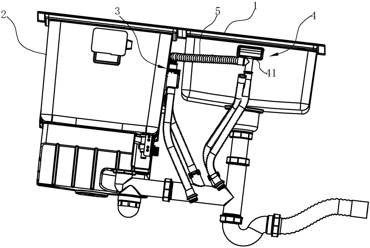
[0023] see Figure 1~4 As shown, the tank type cleaning device includes a first tank 1 and a second tank 2, wherein a cleaning mechanism is arranged in the second tank 2, and the cleaning mechanism can adopt the prior art, such as the applicant described in the background technology The Chinese patent whose application number is 201320889945.4. The first water tank 1 is an ordinary household water tank.

[0024] An air-permeable structure is provided between the side walls of the first water tank 1 and the second water tank 2 , and the air-permeable structure communicates the second water tank 2 with the first water tank 1 . The ventilation structure includes an exhaust assembly 3 arranged on the side wall of the second water tank 2, an air intake assembly 4 arranged on the side wall of the first water tank 1, and a ventilation pipe connecte...


PUM


Abstract

The invention relates to a sink type cleaning device which comprises a first sink, a second sink internally provided with a cleaning mechanism, and a ventilation structure. The ventilation structure comprises an exhaust assembly arranged on the side wall of the second sink, an air inlet assembly arranged on the side wall of the first sink, and a ventilation pipe connecting the exhaust assembly with the air inlet assembly, the exhaust assembly is communicated with fluid inside the second sink, and the air inlet assembly is communicated with fluid inside the first sink. The sink type cleaning device is characterized in that the air inlet assembly is provided with a condensation assembly for condensing fluid and arranged to be used for condensing at least partial water vapor in the fluid drained through the air inlet assembly. Compared with the prior art, the sink type cleaning device has the advantage that the steam is condensed on the condensation assembly, water can flow out of the airinlet assembly along the condensation assembly and finally flows into the first sink, the phenomenon that condensed water flows into an air inlet of the air inlet assembly is avoided, the requirementfor the dish-washing machine performance standard is met, and the phenomenon that due to the fact that direction ventilation is caused to a cabinet, moist, mildew and damage are caused to the cabinetis avoided.

Description

technical field [0001] The invention relates to a machine for automatically cleaning tableware, in particular to a condensing mechanism of a sink type washing machine. Background technique [0002] Today's dishwashers have begun to use steam to clean dishes. Compared with using heated water, using steam also reduces the washing time and improves the washing effect. [0003] In order to save space, there have been many sink-type washing machine designs, that is, the existing sink is converted into a washing machine, and the sink is directly used as the washing space. Generally, a rotating spray arm is arranged at the bottom of the sink. Connect a pump driven by a motor. For example, the applicant’s application number is 201320889945.4, which discloses a sink type cleaning machine, which includes a box body forming a washing space. The box body includes a sink body and a cover plate that is rotatably connected to the sink body. The bottom of the sink body is at least There i...

Claims


Application Information

Patent Timeline
Patent Type & Authority Applications(China)
IPC IPC(8): A47L15/00A47L15/42
CPCA47L15/0086A47L15/42A47L2601/04
Inventor 徐慧刁硕茅忠群诸永定
Owner NINGBO FOTILE KITCHEN WARE CO LTD
Why Eureka
Try Eureka