A planning method for fdm printing path

A printing path and planning technology, applied in the direction of 3D object support structure, manufacturing tools, processing data acquisition/processing, etc., can solve the problems of high printing path speed, affecting printing quality, and reducing printing efficiency, so as to improve printing efficiency and eliminate Repeated printing, the effect of reducing the amount of extrusion

Active Publication Date: 2019-12-20
NINGXIA KOCEL MOLD
View PDF6 Cites 0 Cited by
  • Summary
  • Abstract
  • Description
  • Claims
  • Application Information

AI Technical Summary

Problems solved by technology

At present, the printing path is mostly linear printing, refer to figure 1 As shown, the direction of the arrow is the printing path, and the resulting printing path has many defects: 1) When printing corners and corners, the extrusion volume is too large and the printing path speed is too high, resulting in accumulation of corners and corners, resulting in accumulation, Seriously affect the printing quality; cause repeated printing, and reduce printing efficiency; 2) Printing runs in a single direction in a straight line, printing can only be from left to right, and there are jumps in the blank area (cavity) in the middle, and the knife is raised many times, reducing printing Efficiency; 3) The starting point of the printing path is unique, resulting in multiple lifts of the knife, wasting running time, and causing accumulation of defects

Method used


Image

  • A planning method for fdm printing path
  • A planning method for fdm printing path
  • A planning method for fdm printing path

Examples


Embodiment Construction

[0028] In order to enable those skilled in the art to better understand the technical solutions of the present invention, the present invention will be further described in detail below in conjunction with specific embodiments. The embodiments described below are exemplary, and are only used to explain the present invention, but should not be construed as limiting the present invention. Where specific techniques or conditions are not indicated in the embodiments, the procedures shall be carried out in accordance with the techniques or conditions described in the literature in the field or in accordance with the product specification.

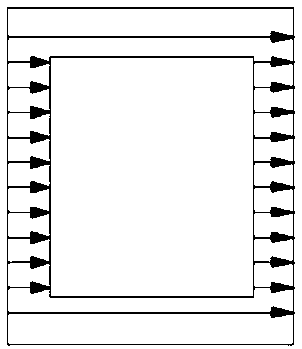
[0029] Currently, the printing path is mostly linear printing, figure 1 Schematic diagram of linear printing in the prior art, refer to figure 1 As shown, the arrow direction is the printing path, and the resulting printing path has many defects: 1) When printing corners and corners, the extrusion amount is too large and the printing path speed is t...


PUM


Abstract

The invention relates to a planning method of an FDM printing route. The planning method mainly comprises the following steps: firstly, guiding a mold, afterwards performing layered sectioning, setting the thickness of each layer and obtaining outline data of each two-dimensional planar image layer; and secondly, generating printing routes; transforming the data of each two-dimensional planar image layer into an equipment printing program, and generating corresponding printing routes according to the outline data of each two-dimensional planar image layer when executing a program language, wherein the printing routes include a linear type printing route and a regional reciprocating type printing route. By adopting the planning method provided by the invention, an sectioning engine is optimized so that the printing route speed at corners and edges is reduced, the extrusion output is also reduced, so high-quality corners and edges can be obtained, generation of stacked burls is prevented, repeated printing is completely eradicated, and thus the printing efficiency is improved; and meanwhile, the cutter lifting frequency is reduced, the running time of each printing route is shortened, the printing period is shortened, and the printing efficiency is improved.

Description

Technical field [0001] The invention belongs to the field of FDM printing technology, and relates to a method for printing a path, in particular to a method for planning a printing path during FDM printing. Background technique [0002] One of the core technologies of additive manufacturing is slicing software. The FDM mold printing path is to convert STL format files into a file format recognized by the printing device through the software, such as .x3d, .Gcode, etc. Currently, the commonly used slicing software in the FDM field converts STL format files into .Gcode format files. STL file is a file format used to represent triangular meshes in computer graphics application systems. It uses a triangular grid to represent the three-dimensional digital model. The STL file stores the information of countless spatial triangles (in space, each triangle is determined by the coordinates of its three fixed points). Therefore, cutting a three-dimensional digital model is actually to use...

Claims


Application Information

Patent Timeline
Patent Type & Authority Patents(China)
IPC IPC(8): B29C64/386B29C64/118B33Y50/00
CPCB33Y50/00
Inventor 王志勇杨保苏建民柏长友撖俊虎
Owner NINGXIA KOCEL MOLD
Why Eureka
Try Eureka