Automatic adhesive tape pasting machine

An automatic tape application technology, applied in the field of automatic tape application machines, can solve problems such as expanding operators, reducing efficiency, and defective products

Pending Publication Date: 2018-05-22
苏州德睿联自动化科技有限公司
View PDF13 Cites 14 Cited by
  • Summary
  • Abstract
  • Description
  • Claims
  • Application Information

AI Technical Summary

Problems solved by technology

[0002] Adhesive tape products need to be pasted on the surface, especially on glass products involving high-precision solar cell strings. Under the premise of today's large demand in the market, there are still manual pasting, in order to achieve the output of tape pasting. It does not expand the number of operators, but also increases the labor intensity of manual pasting personnel. When the requirements are high or when people are tired, there will often be a large number of defective products, which will lead to rework or scrapping. Customers cause great economic losses and decline in product reputation
[0003] Later, after some industrial improvements, the use of mechanical working methods to achieve the purpose of sticking tapes, one of the existing tape head mechanisms is that the tape roll and the tape sticking mechanism are separated, the tape roll is in a fixed position, and the tape sticking mechanism sticks each The tape must be returned to the tape position to pick up materials, which wastes time and reduces efficiency; one is that although the tape roll and the tape are moved together, since there is only one suction nozzle, the suction nozzle can only be used again after the tape application is completed. Suction the next tape, same not efficient

Method used


Image

  • Automatic adhesive tape pasting machine
  • Automatic adhesive tape pasting machine
  • Automatic adhesive tape pasting machine

Examples


Embodiment Construction

[0027] The present invention will be described in detail below with regard to specific accompanying drawings.

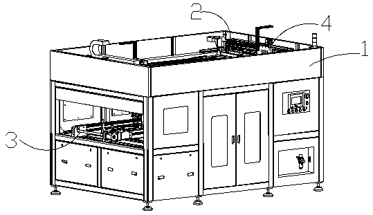
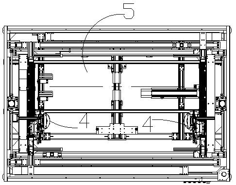
[0028] Such as Figure 1-Figure 5 Shown is a kind of automatic adhesive tape machine, it is characterized in that: comprise frame 1, be provided with manipulator transfer mechanism 2 above described frame 1, be provided with conveying correcting mechanism 3 below described frame, in A taping tape head mechanism 4 is connected on the described manipulator transfer mechanism 2; wherein:

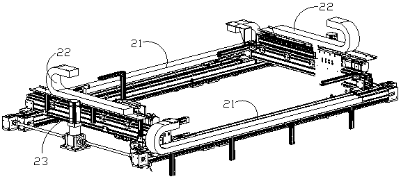
[0029] The manipulator transfer mechanism 2 includes a set of horizontal stepping belts 21 and a set of longitudinal stepping belts 22. The horizontal stepping belts 21 are driven by X-axis motors placed oppositely, and the longitudinal stepping belts 22 are driven by Y-axis motors arranged in parallel. Shaft motor 23 drives;

[0030] Conveying and reforming mechanism 3 comprises reforming frame 31, the conveyer belt 32 that is arranged on the reforming frame, is provided with long ...


PUM


Abstract

The invention relates to an automatic adhesive tape pasting machine. The automatic adhesive tape pasting machine includes a rack, a mechanical arm moving and carrying mechanism arranged above the rack, a conveying and reforming mechanism arranged under the rack, and adhesive tape end pasting mechanisms connected to the mechanical arm moving and carrying mechanism. The automatic adhesive tape pasting machine is used for pasting an adhesive tape onto glass in a solar cell series group; bidirectional movement can be achieved through an X axial motor and a Y axial motor in the mechanical arm moving and carrying mechanism, adhesive tape pasting in the same direction and opposite direction can be achieved, and a pasting position of the adhesive tape is flexible; the conveying and reforming mechanism reforms the glass operating on a reforming rack; the adhesive tape can reach a designated length under the action of an adhesive tape pulling mechanism, a suction nozzle sucks the adhesive tape downward, a cutter drops to cut off the adhesive tape, the adhesive tape is released by the adhesive tape pulling mechanism, a right suction nozzle raises and rotates to a left adhesive tape pasting position, the motor falls to push the nozzle to fall, and the adhesive tape is pasted onto the glass for some time, the motor raises; and while the adhesive tape is pasted, and the right part can pick an adhesive tape.

Description

technical field [0001] The invention relates to an automatic tape sticking machine. Background technique [0002] Adhesive tape products need to be pasted on the surface, especially on glass products involving high-precision solar cell strings. Under the premise of today's large demand in the market, there are still manual pasting, in order to achieve the output of tape pasting. It does not expand the number of operators, but also increases the labor intensity of manual pasting personnel. When the requirements are high or when people are tired, there will often be a large number of defective products, which will lead to rework or scrapping. Customers cause great economic losses and decline in product reputation. [0003] Later, after some industrial improvements, the use of mechanical working methods to achieve the purpose of sticking tapes, one of the existing tape head mechanisms is that the tape roll and the tape sticking mechanism are separated, the tape roll is in a fi...

Claims


Application Information

Patent Timeline
Patent Type & Authority Applications(China)
IPC IPC(8): B65H37/00
CPCB65H37/00B65H2701/194
Inventor 高宜江左佰洋孙海建雷水德
Owner 苏州德睿联自动化科技有限公司
Why Eureka
Try Eureka