Walking wheel composite structure and driving walking wheel and driven walking wheel using same

A composite structure and traveling wheel technology, applied in the directions of traveling mechanism, load hanging components, transportation and packaging, etc., can solve the problems of heavy cast steel traveling wheels, unfavorable production operations, and difficulty in moving, etc. The effect of rail gnawing and noise reduction

Pending Publication Date: 2018-05-22
宁波市凹凸重工有限公司
View PDF0 Cites 0 Cited by
  • Summary
  • Abstract
  • Description
  • Claims
  • Application Information

AI Technical Summary

Problems solved by technology

The material of the traditional traveling wheel generally adopts ZG430-640 cast steel, the main forms of damage are wear, hardened layer crushing and pitting, the noise is loud during operation, and the phenomenon of rail gnawing is serious
In addition, cast steel walking wheels are heavy, and it is difficult for an adult man to move them alone, which is not conducive to production operations

Method used


Image

  • Walking wheel composite structure and driving walking wheel and driven walking wheel using same
  • Walking wheel composite structure and driving walking wheel and driven walking wheel using same
  • Walking wheel composite structure and driving walking wheel and driven walking wheel using same

Examples


Embodiment 1

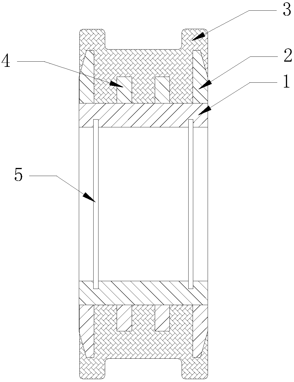
[0029] Embodiment 1: A passive walking wheel, including four structures, a cylindrical wheel core 1, a defective annular fillet welded on the side surface of the wheel core 1, vacuum injection molded on the wheel core 1 and the insert The engineering plastic 3 on the outer layer of the side of the bar, and the groove 5 used for installation on the inner side of the wheel core 1.

[0030] Such as figure 1 , the groove 5 is annular, set inside the wheel core 1, the annular surface is parallel to the bottom surface of the road wheel, and the distances between the two grooves 5 and the two bottom surfaces are equal. In fact, this structure is only to adapt to the application Mechanically mounted, so the structure is not fixed. There are four moldings, two inner moldings, two side moldings 2, the side moldings 2 are set at both ends of the side of the wheel core 1, and the inner layer of the wheel rim; the inner molding A4 is set between the side moldings 2 Between, the inner mol...

Embodiment 2

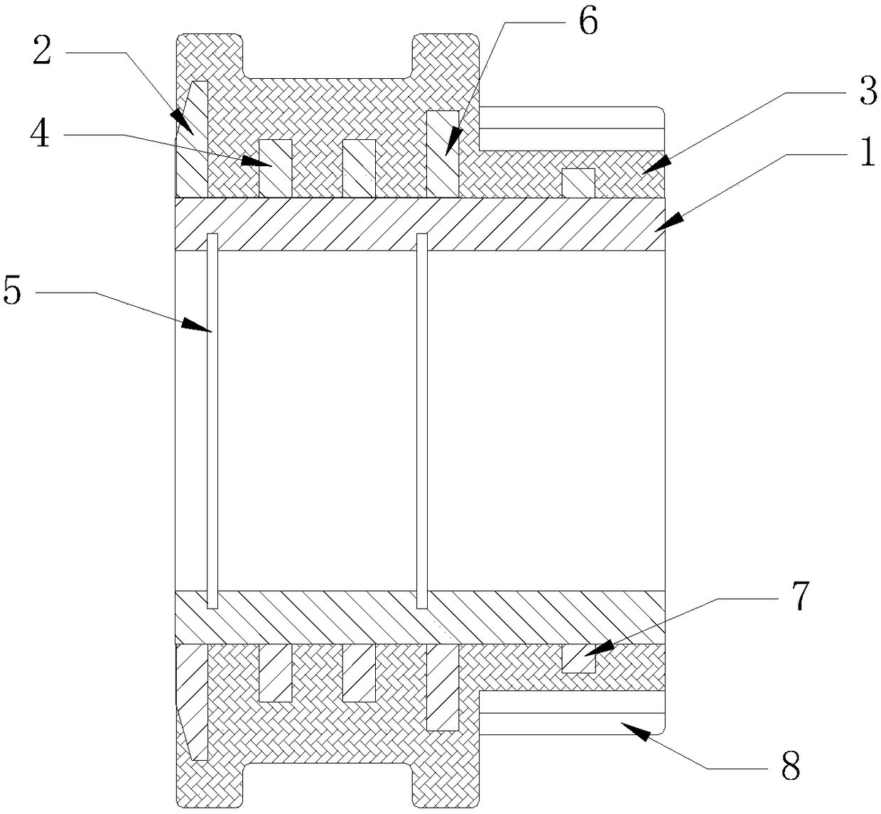
[0034] Embodiment 2: A kind of driving wheel, also includes four kinds of structures, cylindrical wheel core 1, defective ring-shaped fillet welded on the side surface of wheel core 1, injection molded on wheel core 1 and insert The engineering plastic 3 on the outer layer of the side of the bar, and the groove 5 used for installation on the inner side of the wheel core 1. The feature is that the integrally formed shape during vacuum injection molding on the engineering plastic 3 has a rack 8 in addition to the wheel rim, and the rack 8 is the main feature that distinguishes the active wheel from the passive wheel.

[0035] In order to adapt to this feature and ensure the stability of the composite structure of the road wheel, it is necessary to make certain adjustments to the position of the fillet and re-explain the position of the wheel rim. Such as figure 2 , the engineering plastics 3 includes two shapes of two rims and rack 8, wherein one rim and rack 8 are respectivel...


PUM


Abstract

The invention discloses a walking wheel composite structure. The composite structure comprises an insert and engineering plastic, the engineering plastic is attached to the outer layer of the side surface of the insert in an injection molding mode, wherein the insert comprises a wheel core and an embedding strip, the embedding strip is stably connected to the outer surface of the wheel core, and adefect structure is arranged on the embedding strip. The invention further discloses a driving walking wheel and a driven walking wheel which use the composite structure. According to the structure,the driving walking wheel and the driven walking wheel, the self-lubricating property and the wear-resisting property of the using material are brought into full play, and the noise and the rail gnawing phenomenon in the running process are reduced.

Description

【Technical field】 [0001] The invention relates to a wheel, in particular to a compound structure of a road wheel and an active road wheel and a passive road wheel using the structure. 【Background technique】 [0002] The road wheel is a device used to support the crane and load, and to make the crane reciprocate on the track. It is generally used for low-speed, short-distance transportation vehicles. The material of the traditional traveling wheel is generally ZG430-640 cast steel, the main forms of damage are abrasion, hardened layer crushing and pitting, the noise is loud during operation, and the phenomenon of rail gnawing is serious. In addition, cast steel walking wheels are heavy, and it is difficult for an adult man to move them alone, which is not conducive to production operations. 【Content of invention】 [0003] In view of the technical problems mentioned above, the present invention proposes a road wheel compound and the active road wheel and passive road wheel ...

Claims


Application Information

Patent Timeline
IPC IPC(8): B66C9/08
CPCB66C9/08
Inventor 朱良军苏徐迪罗明臣陈琪
Owner 宁波市凹凸重工有限公司
Why Eureka
Try Eureka