Method for Analysis of Glass Defects Using Reflection Electron Probe

A technology of glass defects and reflected electrons, applied in material analysis using wave/particle radiation, material analysis using radiation diffraction, analyzing materials, etc. Simple and quick effect

Active Publication Date: 2020-11-13
DONGXU OPTOELECTRONICS TECH CO LTD
View PDF17 Cites 0 Cited by
  • Summary
  • Abstract
  • Description
  • Claims
  • Application Information

AI Technical Summary

Problems solved by technology

[0004] The purpose of this disclosure is to provide a method for analyzing glass defects using a reflection electron probe, which can well solve the problem of inaccurate positioning of glass defects by existing methods

Method used


Image

  • Method for Analysis of Glass Defects Using Reflection Electron Probe
  • Method for Analysis of Glass Defects Using Reflection Electron Probe
  • Method for Analysis of Glass Defects Using Reflection Electron Probe

Examples


Embodiment

[0039] This example is used to illustrate the analysis of glass defects using the reflection electron probe using the method of the present disclosure.

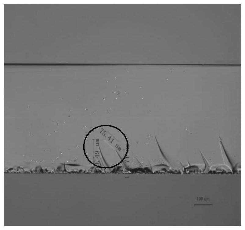
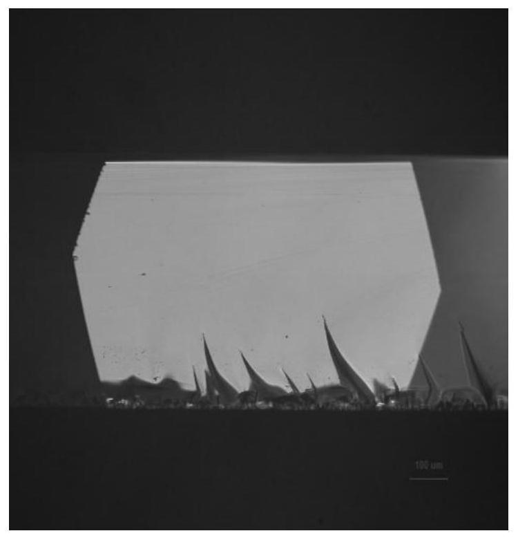
[0040] The glass sample adopted in this embodiment is electronic glass with a thickness of 0.5mm produced by C company, and its photo under a transmission microscope is as follows: figure 1 as shown, figure 1 In the circle, the position of the glass defect is located; the photo under the reflection microscope is as follows figure 2 shown, visible figure 2 No glass defects were observed in the glass.

[0041] Place the above glass sample under an optical transmission microscope, measure the depth of the glass defect from the upper surface of the glass to 111.71 μm, and the depth from the lower surface to 340.81 μm, mark the position of the glass defect on the upper surface of the glass, and obtain the distance from the glass defect as 0.5 ~ 2mm defect mark.

[0042] Place the glass sample on a drawing with cutting markin...


PUM

PropertyMeasurementUnit
thicknessaaaaaaaaaa

Abstract

The disclosure relates to a method for analyzing glass defects using a reflection electron probe, which is characterized in that the method includes the following steps: S1, marking the position of the glass defect and measuring the depth of the glass defect from the glass surface; The glass surface closest to the glass defect is used as a cutting surface, and the cutting surface is cut multiple times with a glass knife to obtain a cut sample with multiple cutting cracks; S3. Observe the cut sample, if there are at least If the distance between one of the cutting cracks and the position of the glass defect is 0-0.55mm, then the cutting crack is used as a characteristic crack for locating the glass defect under the transmission electron microscope; S4, taking the characteristic crack as a reference , using a reflection electron probe to perform positioning analysis on the glass defect. The disclosure well solves the problem of inaccurate defect location in the existing method, and the method is simple and quick without adding additional cost.

Description

technical field [0001] The present disclosure relates to a method of analyzing glass defects using a reflection electron probe. Background technique [0002] At present, TFT glass is an indispensable material for making LCD panels. With the development of technology and the passage of time, people have higher and higher requirements for visual effects, not only requiring fast response, but also high contrast, high resolution and wide viewing angle. Glass defects will affect the yield of glass substrates, therefore, the requirements for reducing the defects of glass substrates are getting higher and higher. [0003] In the existing detection technology, there is no relevant detection method for optical defect detection of glass. Glass optical defects are visible under the microscope, in transmission (eg figure 1 white line in the circle), reflections are not visible (as in figure 2 ), the existing reflection electron probe technology cannot accurately determine the locat...

Claims


Application Information

Patent Timeline
Patent Type & Authority Patents(China)
IPC IPC(8): G01N23/20
CPCG01N23/20G01N2223/102G01N2223/646
Inventor 李志勇李青郑权王丽红闫冬成李俊锋张广涛
Owner DONGXU OPTOELECTRONICS TECH CO LTD
Why Eureka
Try Eureka