Fiber clamping joint on fiber quick-connection joint

A technology of optical fiber clips and connectors, which is applied in the field of communication accessories, can solve the problems of dropping and losing the fixing sleeve, troublesome, unusable optical fiber quick connectors, etc., and achieve the effect of convenient installation, clamping and fixing, and avoiding loss

Inactive Publication Date: 2018-05-22
DONGGUAN LIANZHOU INTPROP OPERATION MANAGEMENT CO LTD
View PDF0 Cites 1 Cited by
  • Summary
  • Abstract
  • Description
  • Claims
  • Application Information

AI Technical Summary

Problems solved by technology

However, in actual use, because the fixing sleeve needs to be removed from the optical fiber quick connector first, the protective layer of the optical fiber is removed, cut, and then matched with the connector seat, and then installed and tightened, the process is relatively troublesome, and During the installation process, the fixed sleeve will be dropped and lost, and the fiber optic quick connector will not be used

Method used


Image

  • Fiber clamping joint on fiber quick-connection joint
  • Fiber clamping joint on fiber quick-connection joint

Examples


Embodiment Construction

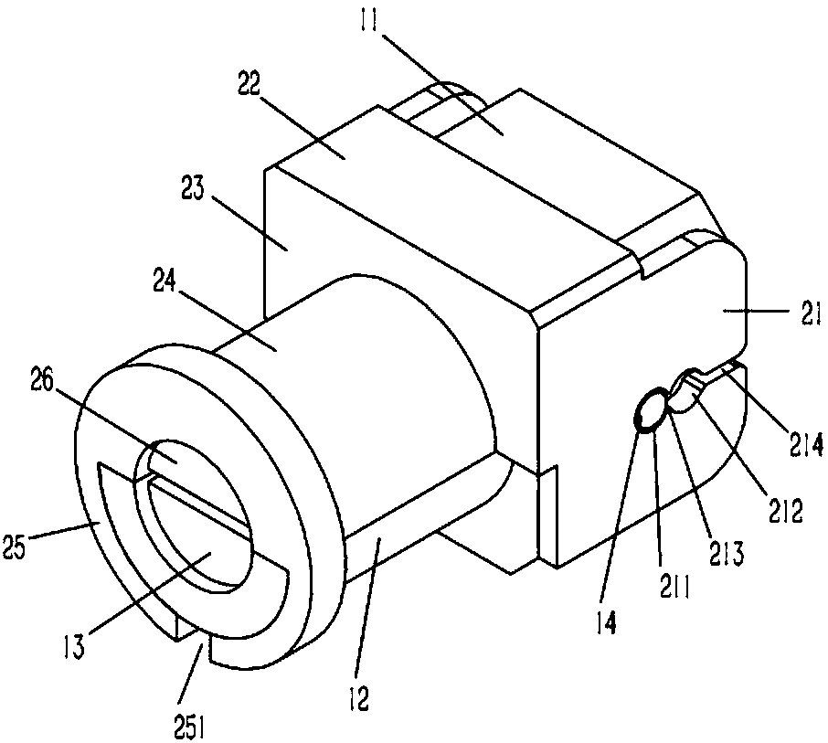
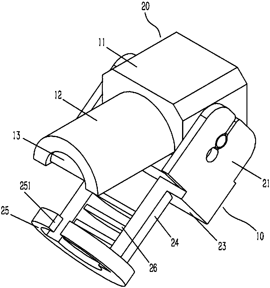
[0016] Example: see figure 1 , 2 As shown, an optical fiber clamping joint on a quick-connect optical fiber joint includes a joint seat 10 and a clamping seat 20. The joint seat 10 includes a rectangular seat body 11, and hinge columns 14 are formed on the two side walls of the seat body 11. A semicircular lower plate body 12 is formed on the front end surface of the seat body 11, and several D-shaped lower clips 13 are formed on the inner wall of the lower plate body 12. Side plate 21, side plate 21 is formed with connected front positioning hole 211 and rear positioning hole 212, hinge column 14 is inserted in the front positioning hole 211 of side plate 21; There is a circular arc transition 213, and the rear end of the rear positioning hole 212 is formed through the wire groove 214 on the rear end surface of the side plate 21; The upper plate body 24, the upper plate body 24 leans against the lower plate body 12 and is a circular post sleeve relative to the lower plate b...


PUM


Abstract

The invention discloses a fiber clamping joint on a fiber quick-connection joint. The fiber clamping joint on a fiber quick-connection joint includes a joint base and a clamping base, wherein the joint base includes a rectangular base body, and a hinge column is moulded on two side walls of the base body; a semi-circular lower plate body is moulded on the front end surface of the base body; a plurality of D type lower clamping pieces are moulded on the inner wall of the lower plate body; the clamping base includes side plates on two side walls of the base body; a front positioning hole and a back positioning hole which are communicated with each other are formed in each of the side plates; the hinge column is inserted in the front positioning holes of the side plates; circular arc transition is formed between the front positioning hole and the back positioning hole; the back end of each back positioning hole penetrates through a wire duct of the back end surface of each side plate; a front panel is moulded on the front end surface of the side plates; a semi-circular upper plate body is moulded on the front end surface of the front panel; the upper plate body abuts against the lowerplate body, and is opposite to the lower plate body to be displayed in an annular column sleeve; an annular limit sleeve is moulded on the outer wall of the front end of the upper plate body; and thelimit sleeve sleeves the lower plate body in an inserted manner. The fiber clamping joint on a fiber quick-connection joint is convenient for mounting, clamping and fixing of fibers, and does not need a fixing sleeve, thus avoiding the situation of losing the fixing sleeve.

Description

Technical field: [0001] The invention relates to the technical field of communication accessories, in particular to an optical fiber holding joint on an optical fiber quick-connect joint. Background technique: [0002] The fiber optic connector permanently or detachably connects two optical fibers together, and has a connecting part of the protective component. The fiber optic connector is the end device of the optical fiber; it is the physical interface used to connect the optical fiber cable. Common optical fiber connectors are generally provided with screwable fixing sleeves, which realize the fixed connection between the connector seat and the clamping seat on the upper and lower sides of the fixing slot; and the fixing sleeve of this structure needs to be fixed first. Set it on the optical fiber, then insert the optical fiber to the connector seat and place it in the fixing slot, close the clamping seat and the connector seat to clamp the optical fiber, and then screw t...

Claims


Application Information

Patent Timeline
Patent Type & Authority Applications(China)
IPC IPC(8): G02B6/38
CPCG02B6/3855
Inventor 孙伟
Owner DONGGUAN LIANZHOU INTPROP OPERATION MANAGEMENT CO LTD
Why Eureka
Try Eureka