
Soldering iron tip cleaner

A cleaner, soldering iron technology, applied in soldering irons, welding equipment, metal processing equipment and other directions, can solve the problem of labor and time

Active Publication Date: 2021-11-02
JAPAN UNIX
View PDF7 Cites 0 Cited by
  • Summary
  • Abstract
  • Description
  • Claims
  • Application Information

AI Technical Summary

Problems solved by technology

[0004] However, the position of the air nozzle and the adjustment of the spraying angle must be arranged so that the air nozzle does not come into contact with the soldering iron tip 1 and the solder supply needle 2, and can accurately spray the solder slag toward the position where the soldering iron tip 1a adheres. It is a very delicate and labor-intensive work that requires precision due to the position and spray angle of the air blowing
Furthermore, because of the positional relationship between the soldering iron tip 1a and the solder supply needle 2, it is difficult to bring the injection port at the tip of the elongated cylindrical air nozzle close to the soldering iron tip, so it is often difficult to directly spray air to the soldering iron tip. , the protruding part of the air nozzle from the cleaner case, the air piping connected to the protruding part, etc. may become obstacles, and it may be difficult to insert the soldering iron tip of the soldering iron into the cleaner case in a correct posture, etc. many

Method used


Image

  • Soldering iron tip cleaner
  • Soldering iron tip cleaner
  • Soldering iron tip cleaner

Examples


Embodiment Construction

[0036] for the manner in which the invention is carried out

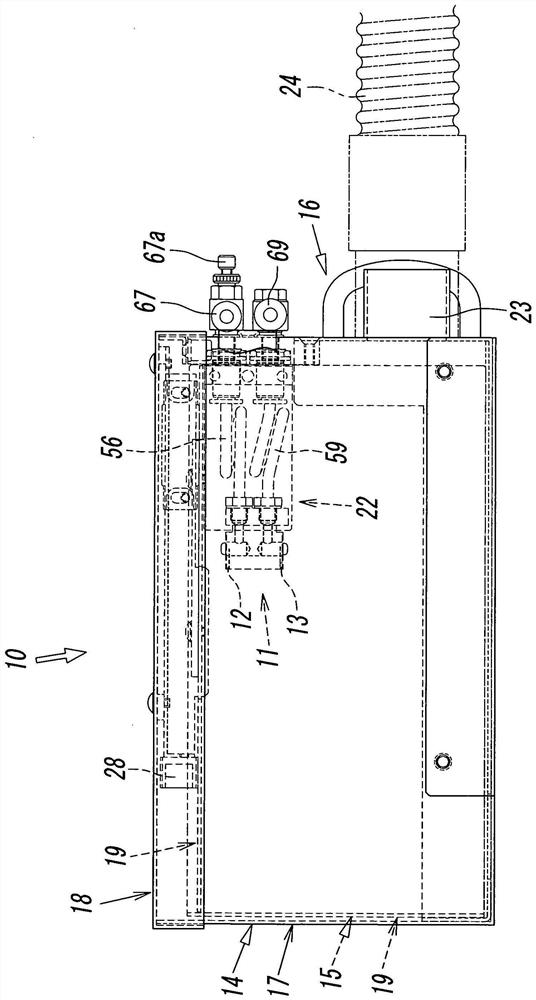
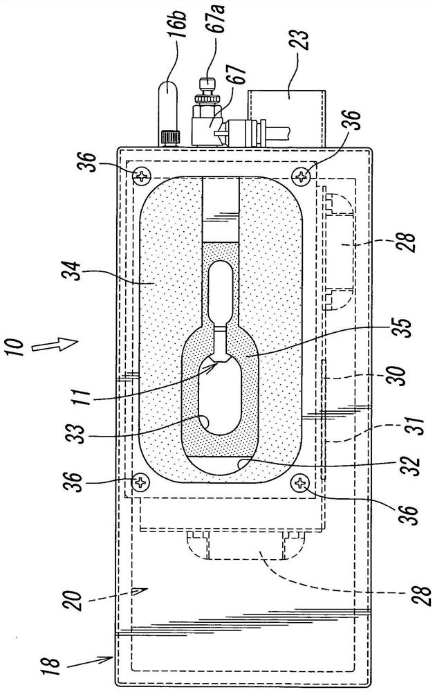
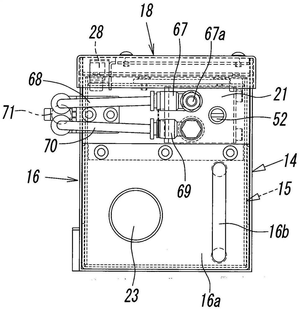
[0037] Figure 1 ~ Figure 3 It is a figure which shows one Embodiment of the soldering iron tip cleaner concerning this invention. This soldering iron tip cleaner, such as Figure 14 and Figure 15 Shown is a cleaner for cleaning the soldering iron tip 1a of a soldering iron 1 adhered to solder slag by spraying air, and has a cleaner box 10 with an air blowing area inside; it is arranged inside the cleaner box 10 The nozzle member 11; and the first nozzle hole 12 and the second nozzle hole 13 opened at the upper and lower end positions of the front end surface of the nozzle member 11.

[0038] The first nozzle hole 12 is a nozzle hole for peeling off the solder slag attached to the soldering iron tip 1a of the soldering iron 1 by spraying air, and the second nozzle hole 13 is used for peeling off the solder slag from the soldering iron tip 1a by spraying air. The peeled-off solder slag falls to the nozzle hole at...


PUM


Abstract

A soldering iron tip cleaner for a soldering iron, the soldering iron tip cleaner peels off the solder slag attached to the soldering iron tip (1a) of a soldering iron (1) by spraying air to clean the soldering iron tip, wherein, The soldering iron tip cleaner has a cleaner box (10) and a nozzle part (11), and the cleaner box (10) has insertion holes (32, 33) for inserting the soldering iron tip of a soldering iron on the top; the nozzle part (11) is housed inside the cleaner box (10), and a first nozzle hole (12) for jetting air toward the tip (1a) of the soldering iron (1) is formed on the nozzle member (11). A nozzle hole (12) consists of a long hole elongated in the horizontal direction.

Description

technical field [0001] The present invention relates to a soldering iron tip cleaner for cleaning a soldering iron tip by blowing air to peel off solder slag adhering to a soldering iron tip of a soldering iron. Background technique [0002] Such a soldering iron tip cleaner is known as disclosed in Patent Document 1, for example. A known soldering iron tip cleaner is configured such that an elongated cylindrical air nozzle provided with a spray port at the tip is inserted into the inside of the cleaner case and the other part is located outside the cleaner case. The posture is installed on the box-shaped cleaner box so that the spray angle can be adjusted freely, and the solder slag attached to the soldering iron tip is sprayed from the jet port to the soldering iron tip of the soldering iron inserted into the cleaner box. Blow away. [0003] On the other hand, soldering irons used in automatic soldering equipment, such as Figure 14 and Figure 15 As shown, each solderi...

Claims


Application Information

Patent Timeline
Patent Type & Authority Patents(China)
IPC IPC(8): B23K3/08
CPCB23K3/028
Inventor 深山智秋
Owner JAPAN UNIX
Learn More