
Fuel spraying device

A fuel injection device and fuel injection technology, applied in the direction of fuel injection devices, fuel injection pumps, low-pressure fuel injection, etc., can solve the problems of increased frequency, fuel injection volume error, engine rotation instability, etc., and achieve the purpose of suppressing torque Changes, reliable fuel suction, and the effect of preventing instability

Active Publication Date: 2009-03-25
MITSUBISHI ELECTRIC CORP
View PDF6 Cites 0 Cited by
  • Summary
  • Abstract
  • Description
  • Claims
  • Application Information

AI Technical Summary

Problems solved by technology

As a result, an error occurs in the amount of fuel injection in each combustion stroke of the engine, and the rotation of the engine becomes unstable.
[0016] In particular, if Figure 13 As shown in (a) and (b), when asynchronous injection is frequently performed compared to synchronous injection, as Figure 13 As shown in (c), the frequency of fuel injection quantity errors per combustion stroke of the engine also increases ( Figure 13 The part shown by the symbol Z in (c), the rotation of the engine is extremely unstable

Method used


Image

  • Fuel spraying device
  • Fuel spraying device
  • Fuel spraying device

Examples


Embodiment Construction

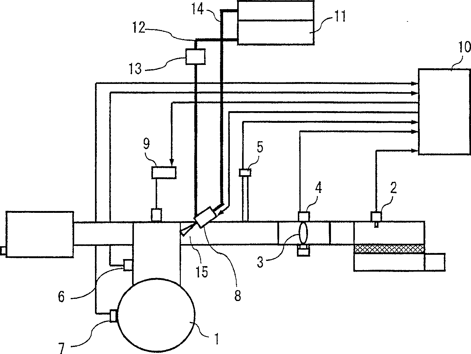
[0035] figure 1 It is a schematic configuration diagram showing the state in which the fuel injection device of the present invention is mounted on the engine in the first embodiment.

[0036] figure 1 Among them, symbol 1 is a four-stroke engine, 2 is an intake air temperature sensor that detects the intake air temperature of engine 1, 3 is a throttle valve, and 4 is a throttle opening sensor that detects the opening degree of throttle valve 3 , 5 is an intake pressure sensor that detects the intake pressure on the downstream side of the throttle valve 3, 6 is an engine temperature sensor that detects the wall surface temperature of the engine 1, and 7 is a crankshaft rotation of the engine 1 (not shown). The crankshaft angle sensor for position detection, 8 is the fuel injection assembly, 9 is the ignition coil, 10 is the control unit.

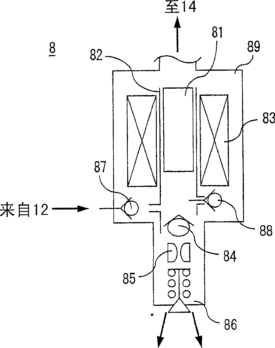
[0037] The fuel injection assembly 8 injects fuel into an intake manifold 15 connected to the engine 1 . Also, the control unit 10 cal...


PUM


Abstract

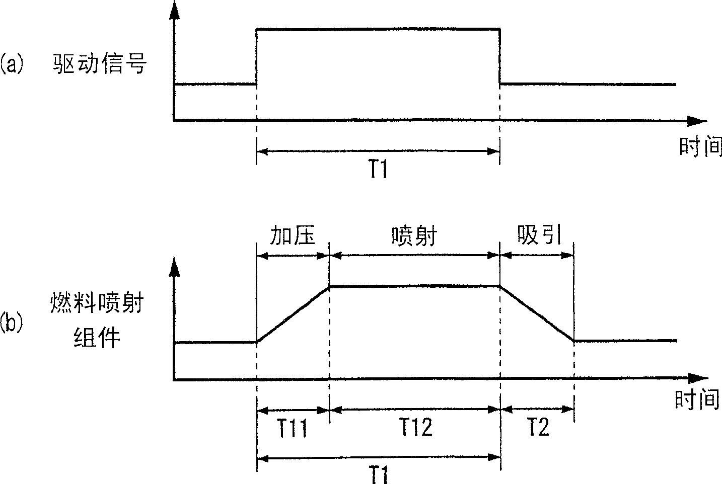
To provide a fuel injector capable of effectively preventing the occurrence of a malfunction of engine rotation by always maintaining a stable fuel injection state in various operation states of an engine. This fuel injector has a fuel injection module 8 for sucking, pressurizing and injecting fuel by reciprocating motion of a plunger 81, and a control unit 10 imparting a driving signal for driving the plunger to the fuel injection module 8 on the basis of the operation state of the engine. The control unit 10 sets maximum driving time being the upper limit of output time of the driving signal so that the sum total (T1+T2) of time required for respective strokes of suction does not exceed a period 2TC of one cycle up to the next intake stroke from a suction stroke of the engine.

Description

technical field [0001] The present invention relates to a fuel injection device having a fuel injection assembly which utilizes the reciprocating motion of a plunger to attract fuel and pressurize it for injection, and in particular to a device for stabilizing the fuel injection state and preventing unstable operation under various operating conditions of the engine. Technology. Background technique [0002] As an electronically controlled fuel injection device that calculates the fuel supply amount according to the engine speed and load and performs fuel injection, a fuel injection unit with a structure has conventionally been proposed (for example, refer to Patent Document 1): The driving signal energizes the solenoid coil, and the plunger is moved by the electromagnetic force generated in the solenoid coil, thereby pressurizing the fuel and injecting it into the intake manifold, and then attracting when the plunger is pushed back by the spring. Fuel behind. [0003] A f...

Claims


Application Information

Patent Timeline
Patent Type & Authority Patents(China)
IPC IPC(8): F02D1/02F02D41/34F02M51/04F02M69/00
Inventor 松野平笃志和田修一山川智也
Owner MITSUBISHI ELECTRIC CORP
Learn More