
Transport conversion mode

A technology for transporting vehicles and pivoting, applied in the direction of transportation and packaging, steering rods, steering mechanisms, etc.

Active Publication Date: 2018-05-25
WIRTGEN GMBH
View PDF9 Cites 0 Cited by
  • Summary
  • Abstract
  • Description
  • Claims
  • Application Information

AI Technical Summary

Problems solved by technology

Drawbacks of this system include the need to get each track off the ground individually one at a time and the need to readjust the steering after adjusting the leg orientation

Method used


Image

  • Transport conversion mode
  • Transport conversion mode
  • Transport conversion mode

Examples


Embodiment Construction

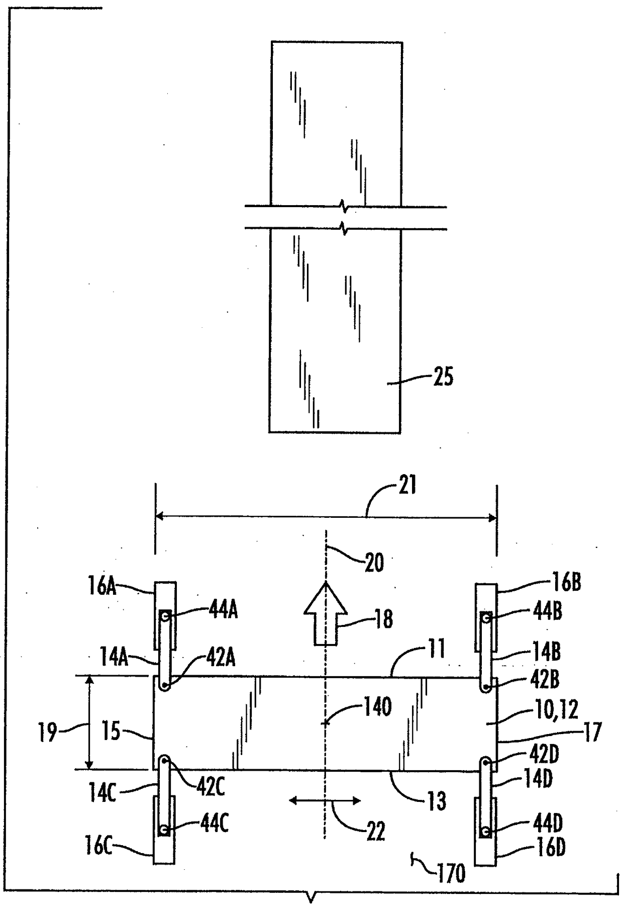
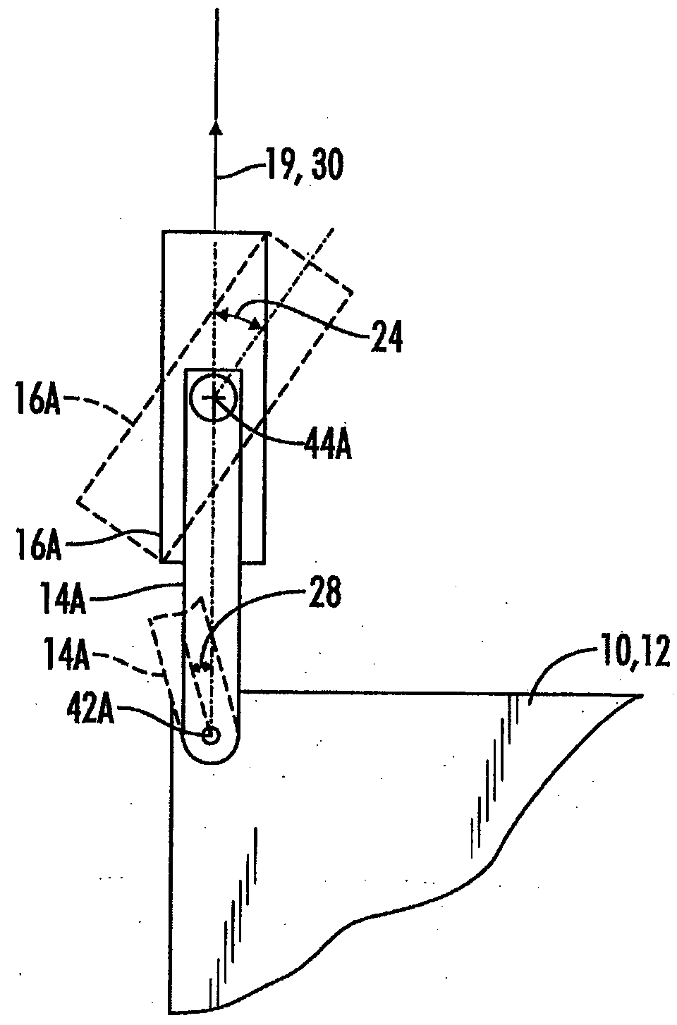
[0041] Figure 1A A self-propelled construction machine 10 is shown schematically. Machine 10 includes a machine frame 12 . The machine frame 12 can be described as having a front 11 , a rear 13 , a left side 15 and a right side 17 . Frame 12 has a frame length 19 defined between front portion 11 and rear portion 13 . The frame 12 has a frame width 21 defined between a left side 15 and a right side 17 .

[0042] Such as Figure 10 As shown schematically in , the construction machine 10 may be a slipform paver having a spreading device 118 arranged to engage concrete blocks 120 formed by a mold 122 such that a formed slab 124 of concrete is slipformed by the machine 10 and laid Exit the rear of Mech 10.

[0043] Figure 10 The slipform paver 10 shown in may be of any conventional construction with respect to its mechanical frame 12 and arrangement of supporting swing legs and tracks. The mechanical frame 12 may be a fixed width frame. The mechanical frame 12 may be a si...


PUM


Abstract

A self-propelled paving machine (10) includes a plurality of swing legs (14A,14B,14C,14D), each swing leg being supported from a ground surface by an associated crawler track (16A,16B,16C,16D) steerably connected to an outer end of its associated swing leg. The machine may be re-oriented from a paving orientation to a transport orientation via a transport conversion mode (200 )of an automatic controller (78) configured to spin the paving in place on the ground through a re-orientation angle, then rotate each of the crawler tracks relative to its respective swing leg until each crawler track isprimarily oriented in a transport direction (22) generally perpendicular to the paving direction (18), and then while moving the paving machine in the transport direction pivoting each of the swing legs relative to the frame (12) until each swing leg is oriented primarily in the transport direction. The paving machine may then be driven onto a transport vehicle (25).

Description

technical field [0001] The present invention relates to methods and apparatus for operating self-propelled construction machines, and more particularly, but not by way of limitation, to methods and apparatus for operating slipform pavers. Background technique [0002] One known arrangement for a self-propelled construction machine comprises a generally rectangular machine frame with oscillating legs mounted at each corner of the frame, and with tracks mounted at the free end of each oscillating leg . Tracks power construction machinery. For various reasons, the mounting of the tracks on the oscillating legs allows the tracks to be repositioned in the horizontal plane relative to the machine frame. For example, a slipform paver using this configuration may require the forward extending swing legs to be extended to make room for a paving tool kit or other equipment supported from the machine frame. Additionally, it may be desirable to reposition one or more swing legs and t...

Claims


Application Information

Patent Timeline
Patent Type & Authority Applications(China)
IPC IPC(8): E01C19/48
CPCE01C19/4886B62D7/1509B62D55/065B62D55/084E01C19/187B62D11/20E01C2301/00E01C19/4893E01C19/48
Inventor M·恩格斯C·莉斯C·巴里马尼
Owner WIRTGEN GMBH
Features
  • Generate Ideas
  • Intellectual Property
  • Life Sciences
  • Materials
  • Tech Scout
  • Unparalleled Data Quality
  • Higher Quality Content
  • 60% Fewer Hallucinations
Learn More