
Low-pressure loss type precession vortex flowmeter spiral flow generator

A precession vortex and spinner technology, which is used in the measurement of flow/mass flow, liquid/fluid solid measurement, volume/mass flow caused by mechanical effects, etc. Increase and other problems, to achieve the effect of wide flow range, simple and compact structure, low pressure loss

Pending Publication Date: 2018-05-25
宁波创盛仪表有限公司
View PDF0 Cites 1 Cited by
  • Summary
  • Abstract
  • Description
  • Claims
  • Application Information

AI Technical Summary

Problems solved by technology

The spinner is also called the vortex generator, which is the core component of the precession vortex flowmeter. Its structure directly affects the pressure loss of the flowmeter. In the actual application process, the pressure loss increases due to the structure of the spinner, and the measurement range is limited. , especially the problem that the accuracy of the flow lower limit cannot be guaranteed. At the same time, during the installation process of the existing spinner, it is easy to deform and break, which is dangerous. Therefore, the structure of the spinner vortex flowmeter is improved to reduce the pressure. It is particularly important to improve the measurement range of the precession vortex flowmeter, ensure the measurement accuracy, and improve the safety factor.

Method used


Image

  • Low-pressure loss type precession vortex flowmeter spiral flow generator
  • Low-pressure loss type precession vortex flowmeter spiral flow generator
  • Low-pressure loss type precession vortex flowmeter spiral flow generator

Examples


Embodiment 1

[0029] Embodiment one, refer to Figure 7 , the spinner is installed in the casing of the screw-in vortex flowmeter, and the front end of the spinner of the screw-in vortex flowmeter is a pressure ring 3, which plays the role of pressing the spinner. Specifically, the pressure ring is threaded in the housing, And the end portion presses the fixing ring, so as to realize the pressing and fixing of the spinner.

Embodiment 2

[0030] Embodiment two, refer to Figure 8 , in this embodiment, and there is an external thread on the side wall, when installing, it is directly fixed in the casing of the vortex flowmeter by threading, reducing the Figure 7 The pressure ring in this embodiment reduces parts and is convenient and quick to install. In order to achieve better strength and reliability, the axial width of the fixing ring in this embodiment can be appropriately enlarged or reduced.

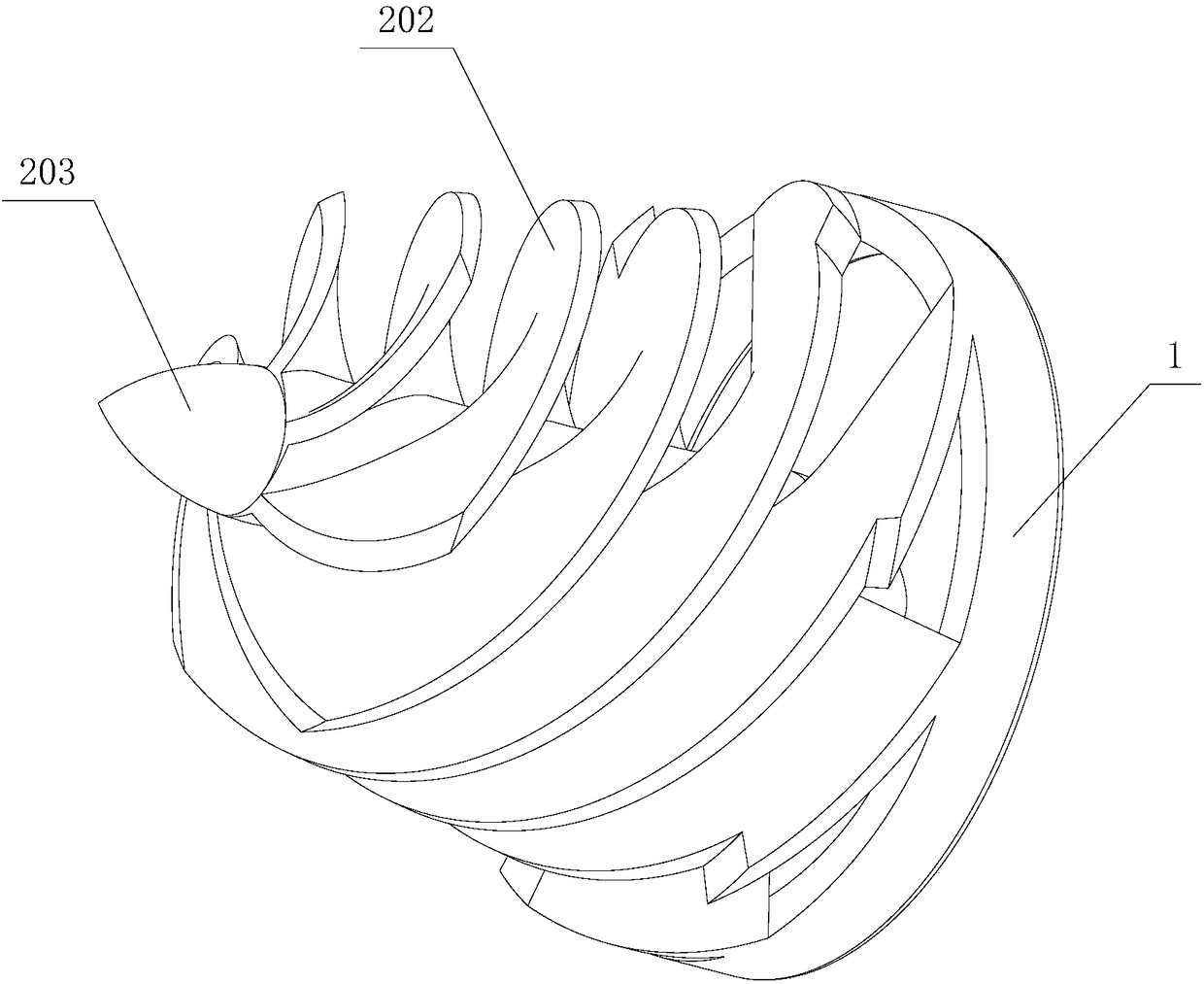
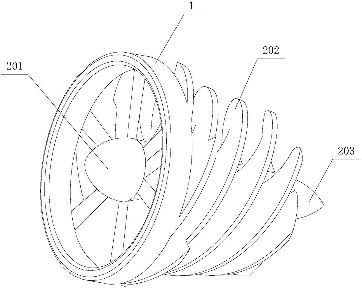
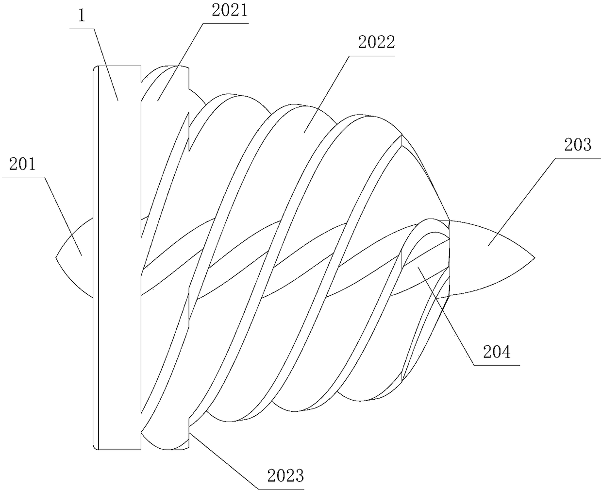
[0031] The spinner of the low-pressure-loss type precession vortex flowmeter of the present invention has a conical structure as a whole, and the middle section of the spinner hub is a conical structure, and there is a taper from front to back, which can make the transition of the fluid flow channel strong. , the pressure loss is reduced; secondly, the vortex strength of the gas entering the flowmeter can be enhanced, which can effectively reduce the measurement lower limit of the flowmeter and widen the flow range; ...


PUM

PropertyMeasurementUnit
Helix angleaaaaaaaaaa

Abstract

The invention provides a low-pressure loss type precession vortex flowmeter spiral flow generator. The spiral flow generator comprises a fixing ring and a spiral flow generator body coaxially fixed onthe fixing ring; the spiral flow generator body comprises a spiral flow generator hub and spiral blades circumferentially and uniformly distributed on the side wall of the spiral flow generator hub,and the head portions of the spiral blades are fixed on the end of the fixing ring; the spiral flow generator hub comprises a circular platform-shaped second hub portion, the diameter of the head portion of the second hub portion is greater than the diameter of the tail portion, two ends of the second hub portion are provided with a first hub portion and a third hub portion respectively, and the first hub portion and the third hub portion are cone-shaped. The spiral flow generator has the advantages of being simple and compact in structure, low in pressure loss, wide in flow range, good in measuring effect, fast and convenient to install, high in structural strength and good in reliability.

Description

technical field [0001] The invention relates to a precession vortex flowmeter spinner, in particular to a low-pressure loss type precession vortex flowmeter spinner. Background technique [0002] The precession vortex flowmeter is a kind of speed flowmeter. It is widely used in the trade measurement of petroleum, chemical industry, electric power, metallurgy, city gas and other industries. It has the characteristics of wide flow range, simple structure, and dirt resistance. Its working principle It uses the vortex precession phenomenon of the fluid to measure the flow rate. The spinner is also called the vortex generator, which is the core component of the precession vortex flowmeter. Its structure directly affects the pressure loss of the flowmeter. In the actual application process, the pressure loss increases due to the structure of the spinner, and the measurement range is limited. , especially the problem that the accuracy of the lower limit of the flow rate cannot be ...

Claims


Application Information

Patent Timeline
IPC IPC(8): G01F1/32
CPCG01F1/3236
Inventor 吕德月曹海彬
Owner 宁波创盛仪表有限公司
Learn More