Jet flow meter using vertical drain flow path and double outlet structure

A double-outlet, flowmeter technology, applied in the direction of volume/mass flow generated by detecting the dynamic effect and mechanical effect of fluid flow, etc., can solve problems such as limiting the range of flowmeter, weak pressure signal strength, and affecting measurement accuracy , to achieve the effect of reducing the lower limit of measurement, reducing interference and improving anti-interference ability

Inactive Publication Date: 2006-05-17
ZHEJIANG UNIV
View PDF0 Cites 0 Cited by
  • Summary
  • Abstract
  • Description
  • Claims
  • Application Information

AI Technical Summary

Problems solved by technology

The planar structure limits its measurement range. When the Reynolds number is small, the viscous force gradually dominates and attenuates the oscillation; in addition, it causes the eddy current to increase. As the eddy current weakens, the velocity field caused by it also weakens. , also attenuates the oscillation; in addition, due to the existence of mechanical vibration and upstream pipeline flow pulsation interference, in this case, it is difficult for the fluid to produce stable jet flow and alternate oscillation, which greatly limits the range of the flowmeter
[0005] (2) For the jet flowmeter with planar structure, due to the single outlet structure directly connected to the rear pipe, the intensity of the pressure signal in the feedback channel is weak, the signal-to-noise ratio is low, and the external environment interferes with the fluid inside the flowmeter It cannot be suppressed, and it is difficult to remove it in the secondary instrument, which obviously affects the accuracy of measurement

Method used


Image

  • Jet flow meter using vertical drain flow path and double outlet structure
  • Jet flow meter using vertical drain flow path and double outlet structure
  • Jet flow meter using vertical drain flow path and double outlet structure

Examples


Embodiment Construction

[0017] The present invention will be further described below in conjunction with drawings and embodiments.

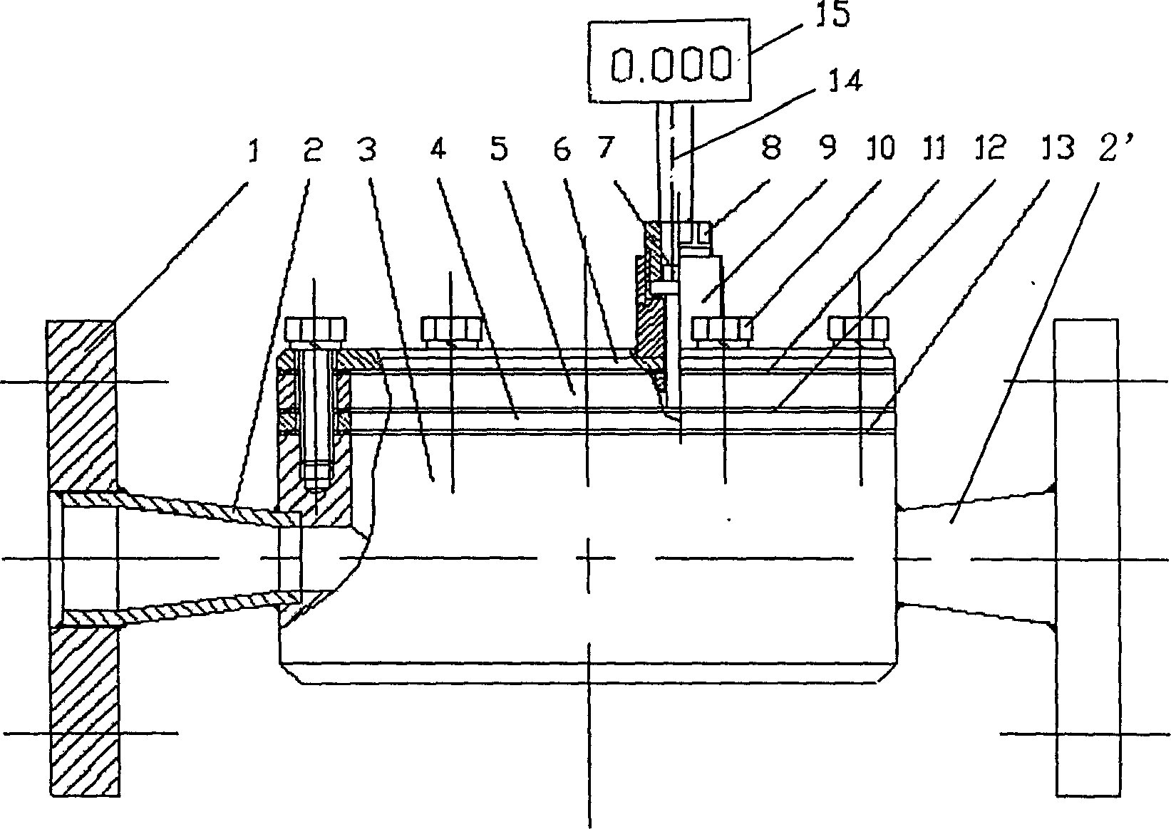
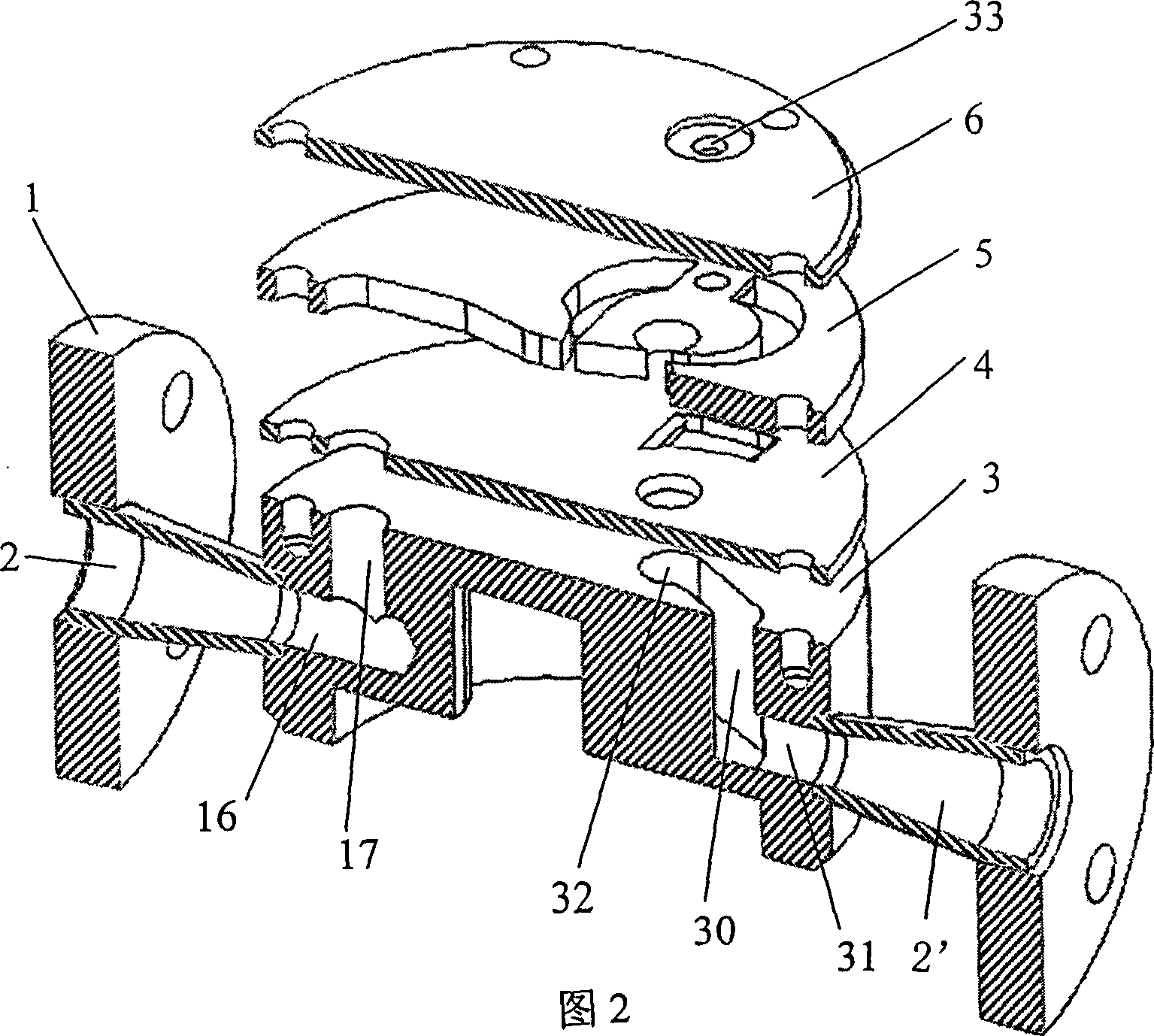
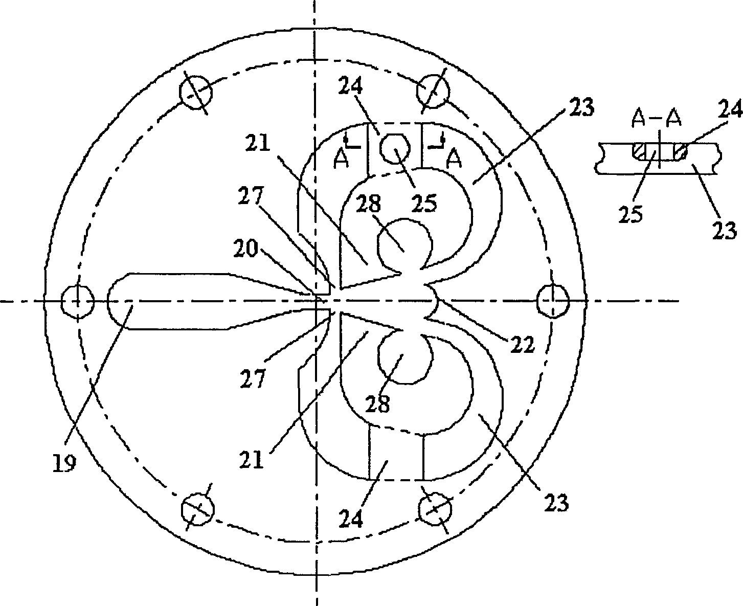
[0018] Such as figure 1 ,figure 2, image 3 and Figure 4 As shown, the present invention provides a jet flowmeter adopting a vertical drainage channel and a double outlet structure, which includes:

[0019] 1) Flange 1, shrinkage tube 2, expansion tube 2', body 3, partition 4, jet part 5, end cover 6, sensor 7, screw 8, boss 9, secondary instrument 15; body 3 is at the entrance It is welded with the shrink tube 2 with flange 1, and the outlet is welded with the expansion tube 2' with another flange 1; the partition 4 and the jet element 5 are horizontally stacked on the upper plane of the body 3 from bottom to top, Above the jet element 5, there is an end cover 6 to fix the partition plate 4 and the jet element 5 on the body 3 through screws 10; 14 is connected with the secondary instrument 15 outside the body 3;

[0020] 2) Inside the body 3, the inlet is compose...


PUM


Abstract

The invention discloses a jet flowmeter adopting a vertical drainage channel and a double outlet structure. Including the body, jet components, sensors and secondary instruments, the inlet of the body is connected with the shrink tube, and the outlet is connected with the expansion tube; there is an ascending channel at the inlet inside the body, and a descending channel at the exit; the jet element is placed horizontally on the plane above the body, There is an end cover above the jet element to fix it on the body through screws; the sensor is set in a feedback loop of the jet element, and is connected with the secondary instrument outside the body through a line. In the present invention, when the fluid passes through the jet plane, the jet wall will induce the fluid to vibrate alternately, and the frequency of the oscillation is proportional to the flow velocity of the jet nozzle. The invention can operate under low pipe Reynolds number, can obtain better signal-to-noise ratio, and has a lower flow measurement lower limit and better anti-interference ability than jet flowmeters with planar structures.

Description

technical field [0001] The invention belongs to fluid metering equipment, in particular to a jet flowmeter adopting a vertical drainage channel and a double outlet structure. Background technique [0002] The emergence of jet flowmeter stems from the development of jet technology. Jet technology developed quite rapidly in the 1960s and 1970s. According to the definition of N12PA (National Fluid Power Association), jet technology is a technology that only uses fluid dynamic phenomena to achieve sensitivity, control, information processing, and functions such as "and" and "or". [0003] At present, jet flowmeters are not widely used in industrial measurement. In foreign countries, jet flowmeters are mostly used to measure viscous liquids with high viscosity and small flow rate, or to measure some cold and hot fluid mixtures and those that are prone to sensor fouling. It is also used in household gas meters or water meters in special occasions such as dirty fluids; the applic...

Claims


Application Information

Patent Timeline
Patent Type & Authority Patents(China)
IPC IPC(8): G01F1/20G01F1/05
Inventor 傅新王驰宇谢海波
Owner ZHEJIANG UNIV
Why Eureka
Try Eureka