
Optical tweezers optical sheet microscopic imaging device and method

A microscopic imaging and optical tweezers technology, applied in microscopes, measuring devices, fluorescence/phosphorescence, etc., can solve the problems of difficult separation of focal planes, high cost, and slow modulation speed

Inactive Publication Date: 2020-05-05
HARBIN INST OF TECH +1
View PDF5 Cites 0 Cited by
  • Summary
  • Abstract
  • Description
  • Claims
  • Application Information

AI Technical Summary

Problems solved by technology

[0002] In conventional objective-type optical tweezers microscopes, the optical tweezers device and the imaging device are usually located on both sides of the sample, which is convenient for separate focusing. However, in some microscopic observation applications that require the introduction of other environmental variables (such as adding radiation The device is used to study the response mechanism of living cells to radiation), and the optical tweezers and the imaging device are required to be located on the same side of the sample. scanning imaging
Adding a zoom lens or DMD to the optical tweezers system can change the focus position of the optical tweezers to solve the above problems, but the modulation speed is slow or expensive

Method used

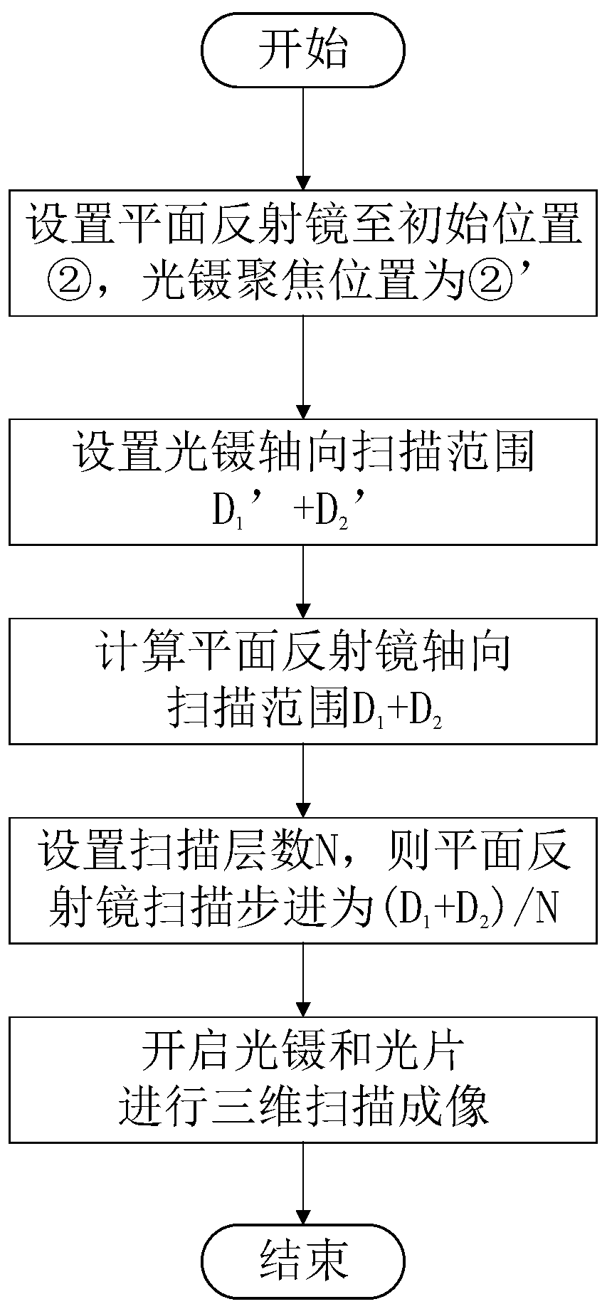

Image

  • Optical tweezers optical sheet microscopic imaging device and method
  • Optical tweezers optical sheet microscopic imaging device and method

Examples


Embodiment Construction

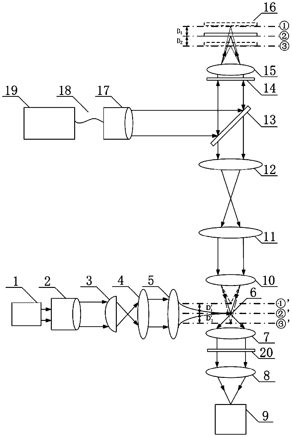
[0026] According to a specific embodiment of the present invention, a measuring device for rapidly switching three-dimensional tomographic scanning in an axial direction is provided, which is used for rapidly switching axial positions to realize three-dimensional tomographic scanning.

[0027] Please refer to figure 1 , figure 1 It is a schematic diagram of an embodiment of the zoom optical tweezers optical sheet micro-imaging device of the present invention. like figure 1 As shown, the zoom optical tweezers microscopic imaging device includes:

[0028] Light sheet illumination module, light sheet detection module, optical tweezers focusing module and optical tweezers axial focusing module:

[0029] According to the light propagation direction, the light sheet lighting module is as follows: laser device-1, beam expander mirror 2, cylindrical mirror 3, tube mirror-4 and objective lens-5;

[0030] According to the light propagation direction, the light sheet detection module...


PUM


Abstract

The invention relates to a zoom optical-tweezer light-sheet microscopy imaging device and method and belongs to the technical field of optical microscopy imaging and optical manipulation. The device comprises a light-sheet illumination module, a light-sheet detection module, an optical-tweezer focusing module and an optical-tweezer axial focusing module. In a conventional optical-tweezer microscope system, an axial focusing device formed by a polarizing beam splitter, a quarter-wave plate, low-aperture objective lenses, tube lenses and a plane mirror is added, thereby realizing axial movementof an optical tweezer focal plane in an optical tweezer light-sheet microscope, realizing axial movement of a grabbed suspension sample and finishing light-sheet three-dimensional tomographic scanningimaging.

Description

technical field [0001] The invention belongs to the technical field of optical microscopic imaging and optical manipulation, and relates to a microscopic imaging device and method of a zoom optical tweezers optical sheet. It can realize separation and focusing of the optical tweezers microscope system and complete three-dimensional light sheet scanning imaging. Background technique [0002] In conventional objective-type optical tweezers microscopes, the optical tweezers device and the imaging device are usually located on both sides of the sample, which is convenient for separate focusing. However, in some microscopic observation applications that require the introduction of other environmental variables (such as adding radiation The device is used to study the response mechanism of living cells to radiation), and the optical tweezers and the imaging device are required to be located on the same side of the sample. scan imaging. Adding a zoom lens or DMD to the optical tw...

Claims


Application Information

Patent Timeline
Patent Type & Authority Patents(China)
IPC IPC(8): G02B21/00G02B21/18G02B21/32G01N21/64
CPCG01N21/6402G01N21/6458G02B21/002G02B21/006G02B21/0068G02B21/0076G02B21/0092G02B21/18G02B21/32
Inventor 刘辰光郑婷婷陈刚谭久彬
Owner HARBIN INST OF TECH
Learn More