
Zoom optical tweezers confocal microscopy imaging device and method

A confocal microscope and imaging device technology, applied in microscopes, optics, optical components, etc., can solve the problems of high cost, difficult separation of focal planes, slow modulation speed, etc., to reduce observation costs, improve zoom and axial layer The effect of analysis speed and simple installation and adjustment

Active Publication Date: 2020-04-28
HARBIN INST OF TECH
View PDF6 Cites 0 Cited by
  • Summary
  • Abstract
  • Description
  • Claims
  • Application Information

AI Technical Summary

Problems solved by technology

[0002] In conventional objective-type optical tweezers microscopes, the optical tweezers device and the imaging device are usually located on both sides of the sample, which is convenient for separate focusing. However, in some microscopic observation applications that require the introduction of other environmental variables (such as adding radiation The device is used to study the response mechanism of living cells to radiation), and the optical tweezers and the imaging device are required to be located on the same side of the sample. scanning imaging
Adding a zoom lens or DMD to the optical tweezers system can change the focus position of the optical tweezers to solve the above problems, but the modulation speed is slow or expensive

Method used


Image

  • Zoom optical tweezers confocal microscopy imaging device and method
  • Zoom optical tweezers confocal microscopy imaging device and method

Examples


Embodiment 1

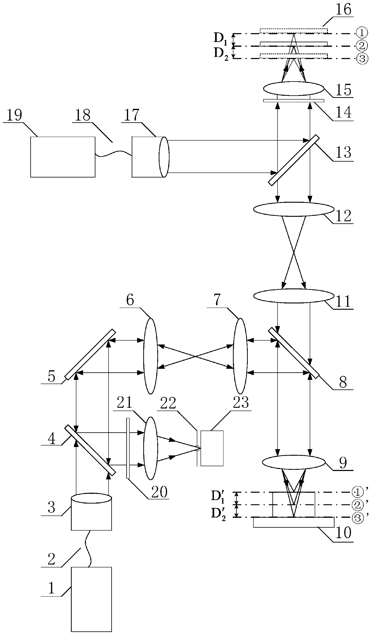
[0030] Embodiment 1: as attached figure 1 The present embodiment shown provides a zoom optical tweezers confocal microscopic imaging device, which is used to quickly switch the axial position to realize three-dimensional tomographic scanning.

[0031] A zoom optical tweezers confocal microscopy imaging device, comprising a confocal illumination module, a confocal scanning module, a confocal detection module, an optical tweezers focusing module and an optical tweezers axial focusing module:

[0032] According to the direction of light propagation, the confocal illumination module is as follows: laser device-1, conduction fiber-2, collimator-3 and dichroic mirror-4;

[0033] The confocal scanning module is in order according to the direction of light propagation: scanning galvanometer 5, scanning lens 6, tube mirror 1 7, dichroic mirror 2 8 and objective lens 1 9;

[0034] The confocal detection module is as follows according to the direction of light propagation: objective len...

Embodiment 2

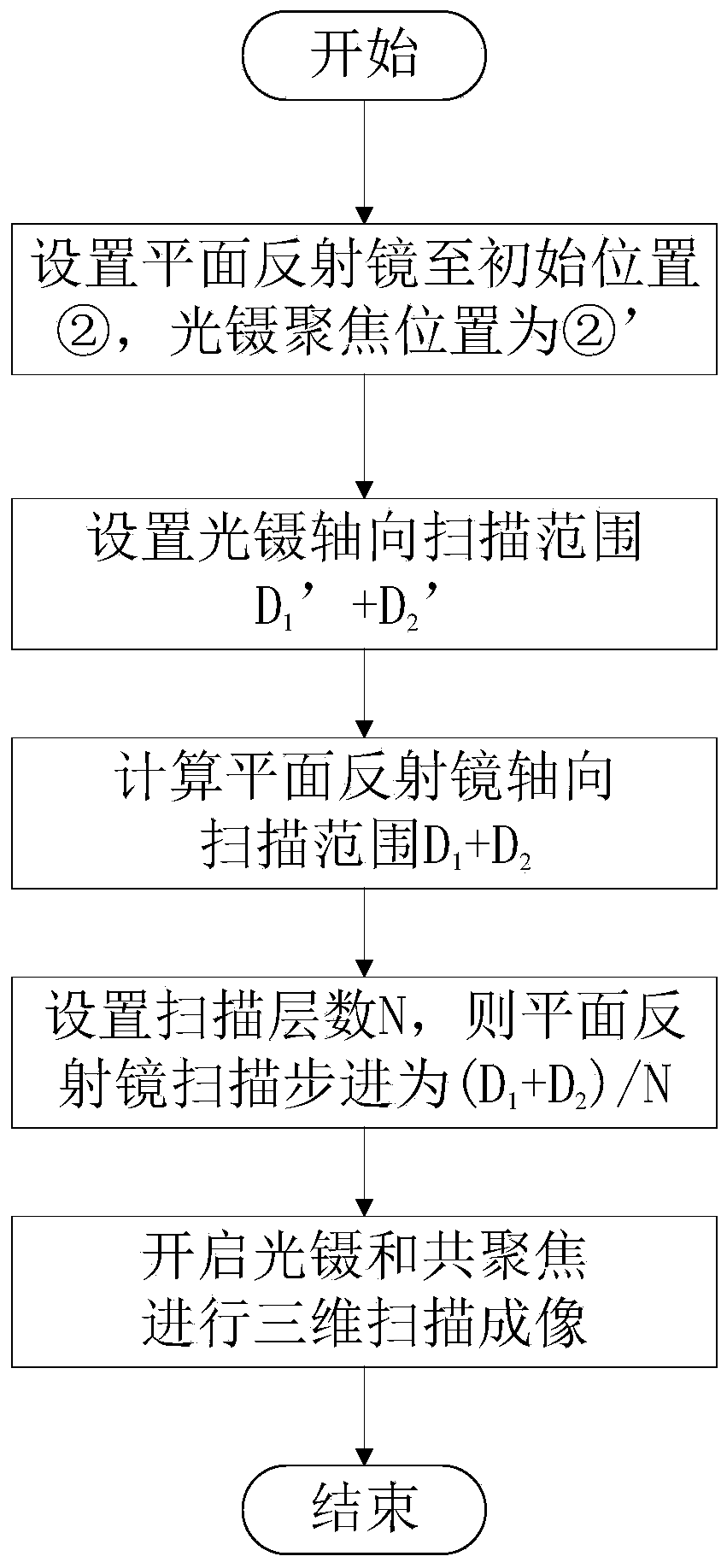
[0046] Embodiment 2: as attached figure 1 and figure 2 The present embodiment shown provides a zoom optical tweezers confocal microscopy imaging method, which is used to quickly switch the axial position to realize three-dimensional tomographic scanning.

[0047] A zoom optical tweezers confocal microscopic imaging method, the method is realized based on the zoom optical tweezers confocal microscopic imaging device described in embodiment 1, specific steps:

[0048] Step a, the laser device-1 emits excitation light, and forms parallel light after passing through the conducting fiber-2 and the collimating mirror-3, and the parallel light beam passes through the dichroic mirror-4, the scanning galvanometer 5, the scanning lens 6, the tube mirror-7, After the dichroic mirror two 8 and the objective lens one 9, a focused spot is formed on the tested sample 10, and the focused spot excites the tested sample 10 to emit fluorescence;

[0049] Step b, the laser device 2 19 emits la...


PUM


Abstract

The invention discloses a confocal microimaging device of zooming optical tweezers and a confocal microimaging method of the zooming optical tweezers, and belongs to the technical field of optical microimaging and optical operation. The confocal microimaging device is technically featured by being composed of a confocal lighting module, a confocal scanning module, a confocal detecting module, an optical tweezers focusing module and an optical tweezers axial zooming module. The regular optical tweezers microscopy system is added with an axial zooming device consisting of a polarizing beam splitter, a quarter-wave plate, a low aperture objective lens, a pipe lens and a plane reflective lens; thus the axial movement of the optical tweezers focal face in the co-path optical tweezers confocal microscopy is realized, thereby grabbing a suspending sample and achieving the axial movement, and completing the confocal three-dimensional chromatography scanning imaging. The confocal microimaging device has the advantages of being simple in assembly, quick in zooming and axial chromatography speed, and low in observing cost.

Description

technical field [0001] The invention relates to a microscopic imaging device and method, in particular to a zoom optical tweezers confocal microscopic imaging device and method, which can realize the separation and adjustment of the co-optical path optical tweezers microsystem and complete three-dimensional confocal scanning imaging, which belongs to optical Microscopic imaging and optical manipulation technology. Background technique [0002] In conventional objective-type optical tweezers microscopes, the optical tweezers device and the imaging device are usually located on both sides of the sample, which is convenient for separate focusing. However, in some microscopic observation applications that require the introduction of other environmental variables (such as adding radiation The device is used to study the response mechanism of living cells to radiation), and the optical tweezers and the imaging device are required to be located on the same side of the sample. scan...

Claims


Application Information

Patent Timeline
Patent Type & Authority Patents(China)
IPC IPC(8): G02B21/00
CPCG02B21/0024G02B21/0028G02B21/0048
Inventor 刘辰光赵一轩刘俭王宇航谭久彬
Owner HARBIN INST OF TECH
Learn More