Radio frequency circuit capable of suppressing harmonics and terminal

A radio frequency circuit and control circuit technology, applied in the field of communications, can solve the problems of B4 downlink interference and complex influence, and achieve the effect of suppressing harmonic signals and suppressing self-interference

Inactive Publication Date: 2018-05-25
SHENZHEN GIONEE COMM EQUIP
View PDF0 Cites 7 Cited by
  • Summary
  • Abstract
  • Description
  • Claims
  • Application Information

AI Technical Summary

Problems solved by technology

[0003] However, in the case of carrier aggregation between frequency bands, since the uplink and downlink signals are in different frequency bands, the impact between them will become very complicated
For example, the harmonics or intermodulation products of a certain frequency band in the transmitting state may fall into another receiving frequency band. For example, for carrier aggregation terminals that support fr

Method used


Image

  • Radio frequency circuit capable of suppressing harmonics and terminal
  • Radio frequency circuit capable of suppressing harmonics and terminal
  • Radio frequency circuit capable of suppressing harmonics and terminal

Examples


Embodiment Construction

[0023] The following will clearly and completely describe the technical solutions in the embodiments of the present invention with reference to the accompanying drawings in the embodiments of the present invention. Obviously, the described embodiments are some of the embodiments of the present invention, but not all of them. Based on the embodiments of the present invention, all other embodiments obtained by persons of ordinary skill in the art without making creative efforts belong to the protection scope of the present invention.

[0024] It should be understood that when used in this specification and the appended claims, the terms "comprising" and "comprises" indicate the presence of described features, integers, steps, operations, elements and / or components, but do not exclude one or Presence or addition of multiple other features, integers, steps, operations, elements, components and / or collections thereof.

[0025] It should also be understood that the terminology used ...


PUM


Abstract

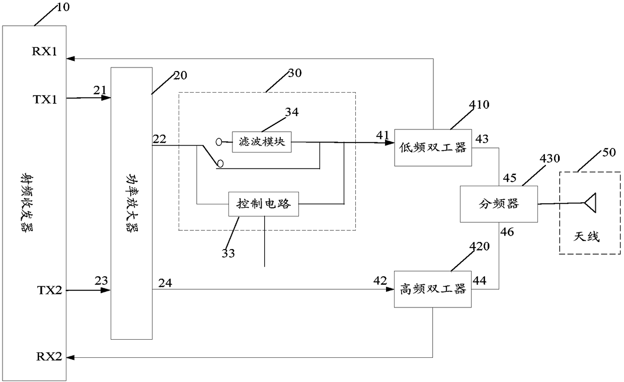
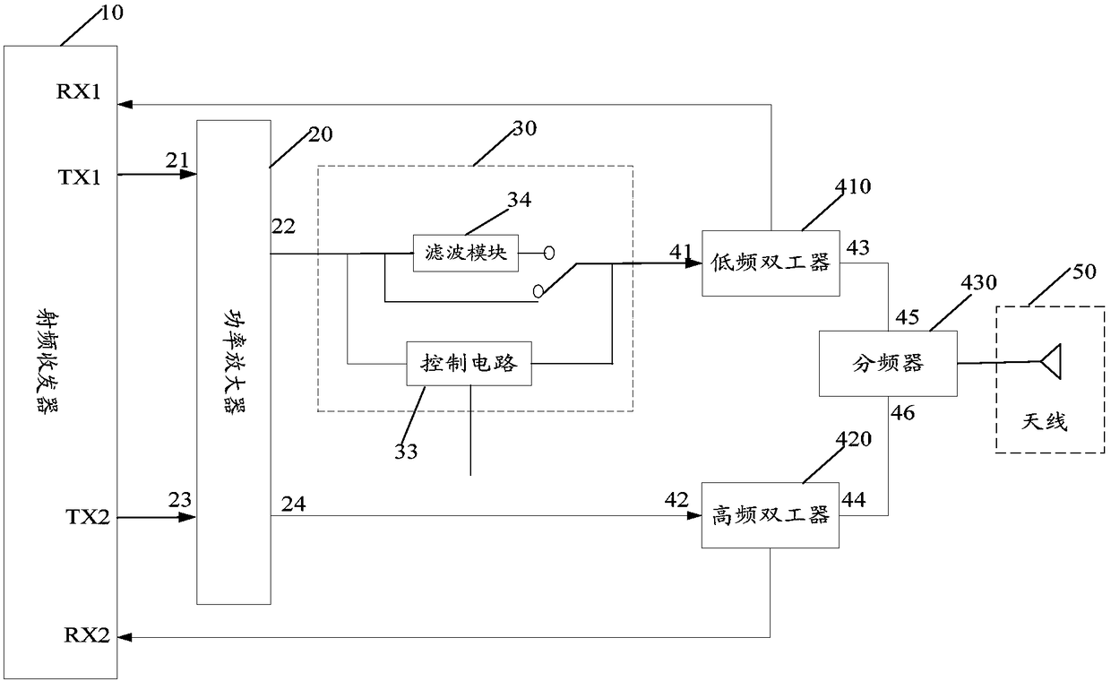
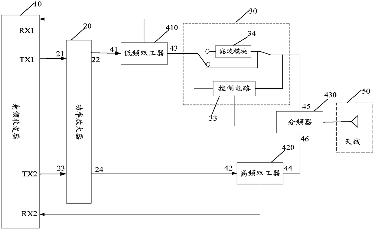
The embodiment of the invention discloses a radio frequency circuit capable of suppressing harmonics and a terminal. The radio frequency circuit comprises a radio frequency transceiver (10), a power amplifier (20), a filtering device (30), a low-frequency duplexer (410), a high-frequency duplexer (420), a frequency divider (430) and an antenna (50); the filtering device (30) comprises a control circuit (33) and a filtering module (34); the TX1 end of the radio frequency transceiver (10) is connected with the 21 end of the power amplifier (20), the 22 end of the power amplifier (20) isconnected with the first end of the filtering device (30), the first end of the filtering device (30) is connected with the 41 end of the low-frequency duplexer (410), and the 43 end of the low-frequency duplexer (410) is connected with the frequency divider (430); the TX2 end of the radio frequency transceiver (10) is connected with the 23 end of the power amplifier (20), the 24 end of the power amplifier (20) is connected with the 42 end of the high-frequency duplexer (420), and the 44 end of the high-frequency duplexer (420) is connected with the frequency divider (430); the third end of the low-frequency duplexer (410) is connected with the RX1 end of the radio frequency transceiver (10), and the third end of the high-frequency duplexer (420) is connected with the RX2 end of the radio frequency transceiver (10); the frequency divider (430) is connected with the antenna (50); and the filtering device (34) can be connected between the 22 end of the power amplifier (20) and the 41 end of the low-frequency duplexer (410) in a selectable mode, and when the control circuit is used for the radio frequency transceiver (10) to send an uplink signal in a first frequency band through carrier aggregation, the control circuit controls the first end of the filtering device (34) to be connected with the 22 end of the power amplifier (20) and controls the second end of a second switch (32) to be connected with the 41 end of the low-frequency duplexer (410). According to the radio frequency circuit, interferences among frequency bands can be suppressed.

Description

technical field [0001] The invention relates to the technical field of communication, in particular to a radio frequency circuit and a terminal for suppressing harmonics. Background technique [0002] With the continuous evolution of the Long Term Evolution (LTE) technology, the enhanced Long Term Evolution (LTE-Advance, LTE-A) technology is becoming more and more popular, especially the carrier aggregation (carrier aggregation (CA) technology). [0003] However, in the case of carrier aggregation between frequency bands, since the uplink and downlink signals are in different frequency bands, the influence between them will become very complicated. For example, the harmonics or intermodulation products of a certain frequency band in the transmitting state may fall into another receiving frequency band. For example, for carrier aggregation terminals that support frequency bands Band4 (hereinafter referred to as B4) and Band12 (hereinafter referred to as B12), Since the corre...

Claims


Application Information

Patent Timeline
IPC IPC(8): H04B1/40
CPCH04B1/40
Inventor 武超
Owner SHENZHEN GIONEE COMM EQUIP
Why Eureka
Try Eureka