Computer numerical control bending machine

A bending machine and frame technology, applied in the field of steel bar bending hoop devices, can solve the problems of limited diameter range of compressed steel bars, encoders easily damaged by vibration, and steel bars are not easy to adjust, etc., and achieves good straightening effect and low vibration. , The effect of not easily damaged by vibration

Inactive Publication Date: 2018-05-29
青岛炫昌能源装备有限公司
View PDF0 Cites 0 Cited by
  • Summary
  • Abstract
  • Description
  • Claims
  • Application Information

AI Technical Summary

Problems solved by technology

[0002] At present, the tool for bending hoops is the hoop bending machine, which was introduced in recent years. However, in the existing hoop bending machines, the modulation plate is generally adjusted in one direction, and the steel bars are not easy to adjust and the speed is slow; and the existing hoop bending machines There is only one pressure cylinder in the drive system, the diameter range of the compression steel bar is limited, and because the motor is installed above the center line of the machine (height direction), the stability is poor, the vibration is large, and the encoder is easily damaged by vibration
The speed of several bending actions of a stirrup is uniform. When processing a stirrup with a long side length, the bending speed must be reduced, which reduces the production efficiency.

Method used


Image

  • Computer numerical control bending machine

Examples


Embodiment Construction

[0018] The following will be further described in conjunction with the accompanying drawings, not to limit the scope of the present invention.

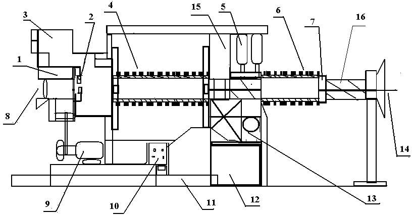
[0019] see figure 1 As shown, the present invention comprises frame 11 and cutting mechanism 1, and a cutting motor 9 is installed on the bottom of frame 11, and described cutting motor 9 provides power for cutting mechanism 1, and the main shaft of described cutting motor 9 passes through a transmission mechanism It is connected with the cutting mechanism 1. A bending hoop mechanism 3 is installed on one side of the cutting mechanism 1, and a split blade 2 is arranged inside the bending hoop mechanism 3. Anaerobic glue is added to the split blade 2 to organically combine the blade and the knife body, eliminating the need for blades Disadvantages of serial movement relative to the cutter body, cost saving, and easy disassembly and assembly. The bending hoop mechanism 3 generally has several bending actions for each hoop. The input sp...


PUM


Abstract

The invention relates to a computer numerical control bending machine. The computer numerical control bending machine comprises a rack, a cutting motor, a rear straightening plate, a front straightening plate and a cutting mechanism, wherein the cutting motor is arranged at the lower part of the rack; the cutting mechanism is arranged at the upper part of the cutting motor; a bending and hooping mechanism is arranged at one side of the cutting mechanism and is connected to the rear straightening plate by a mechanical device; a compressing driving device is arranged at one side of the rear straightening plate and is connected to a line dragging device by a driving shaft; and the line dragging device is provided with a line dragging pole. The computer numerical control bending machine has areasonable driving structure, good stability, small vibration and wide market prospect.

Description

technical field [0001] The invention relates to a steel bar hoop bending device, in particular to a numerically controlled bending machine. Background technique [0002] At present, the tool for bending hoops is the hoop bending machine, which was introduced in recent years. However, in the existing hoop bending machines, the modulation plate is generally adjusted in one direction, and the steel bars are not easy to adjust and the speed is slow; and the existing hoop bending machines There is only one pressure cylinder in the driving system, the diameter range of the compression steel bar is limited, and because the motor is installed above the center line of the machine (height direction), the stability is poor and the vibration is large, and the encoder is easily damaged by vibration. The speed of several bending actions of a stirrup is uniform. When processing a stirrup with a long side length, the bending speed must be reduced, which reduces the production efficiency. ...

Claims


Application Information

Patent Timeline
Patent Type & Authority Applications(China)
IPC IPC(8): B21F1/00B21F1/02B21F11/00
CPCB21F1/00B21F1/026
Inventor 郝新光
Owner 青岛炫昌能源装备有限公司
Why Eureka
Try Eureka