Welding auxiliary device and welding method

A technology of auxiliary devices and bearing parts, applied in welding equipment, roller electrode welding, resistance welding equipment, etc., can solve the problems of uneconomical use, time-consuming and labor-intensive quality, and high transportation costs, achieving time-saving and labor-saving efficiency and wide applicability. , the effect of low cost

Inactive Publication Date: 2018-05-29
HAIWEI ENG CONSTR CO LTD OF FIRSTHIGHWAY ENG CO LTD OF CCCC
View PDF6 Cites 0 Cited by
  • Summary
  • Abstract
  • Description
  • Claims
  • Application Information

AI Technical Summary

Problems solved by technology

[0005] Lifting the main tendons manually is time-consuming and laborious, and the quality is difficult to guarantee;
[0006] The CNC steel cage roll welding machine is used, which has a large volume, high purchase costs, and high transportation costs. It is not economical to use for projects with a small number of pile foundations or projects in remote mountainous areas.

Method used


Image

  • Welding auxiliary device and welding method
  • Welding auxiliary device and welding method
  • Welding auxiliary device and welding method

Examples


Embodiment 1

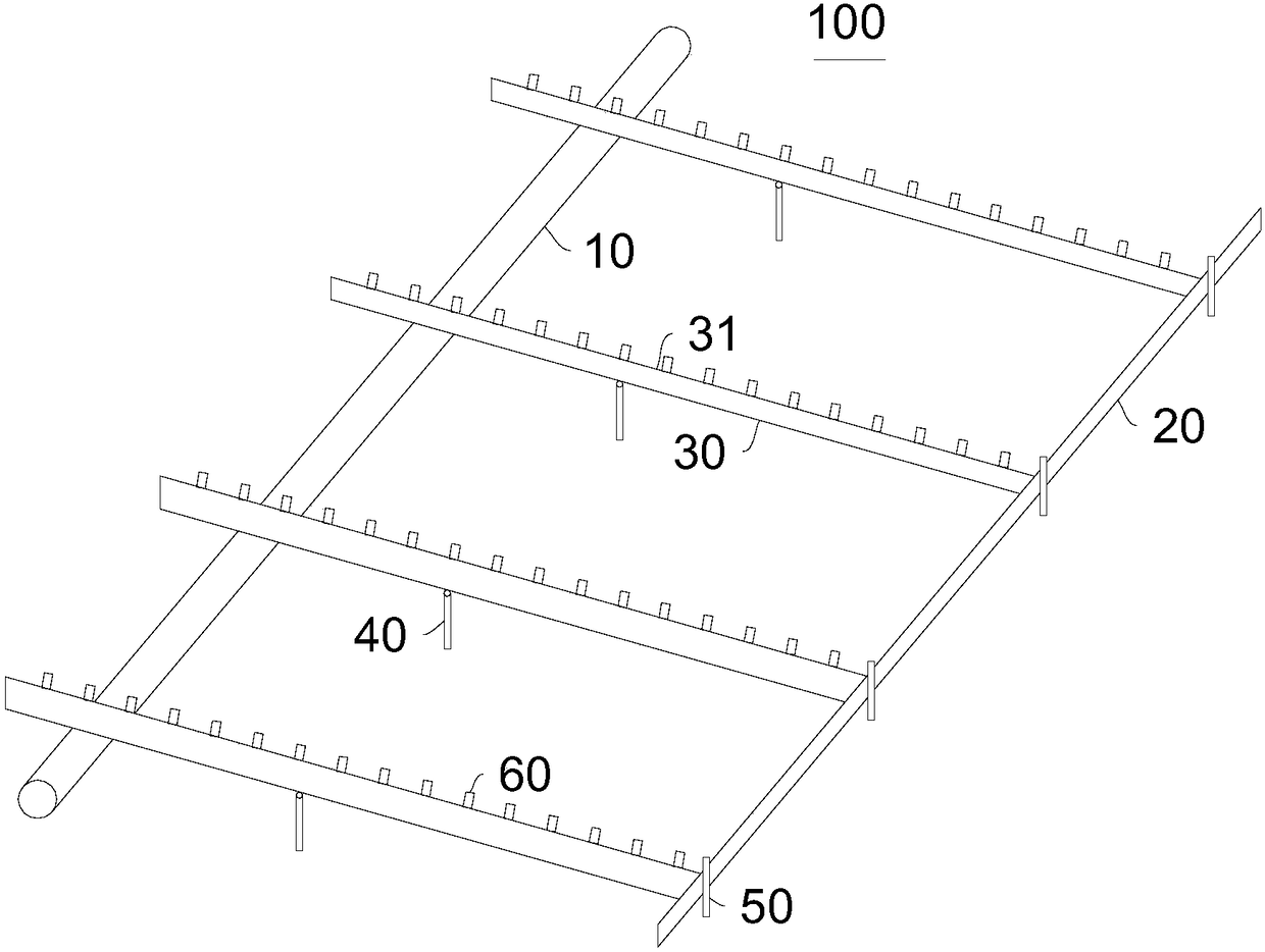
[0041] Please refer to Figure 1-Figure 4 , the present embodiment provides a welding auxiliary device 100, which includes a first fixing part 10, a second fixing part 20 and a plurality of supporting parts 30, one end of the supporting part 30 is connected with the first fixing part 10, and the supporting part 30 The other end is connected with the second fixing part 20, and the supporting part 30 is provided with a plurality of fixing parts 31 for fixing the main rib 200, and the fixing parts 31 are distributed at intervals along the length direction of the supporting part 30, and the plurality of supporting parts 30 are arranged along the first fixing part. 10 are spaced along the length direction.

[0042] In this embodiment, the first fixing part 10 is a spiral steel pipe, the second fixing part 20 is a channel steel, and the bearing part 30 is an I-shaped steel. These materials are common in construction sites. Of course, in other embodiments, any rod or pipe can be use...

Embodiment 2

[0071] This embodiment also provides a welding method, which uses the above-mentioned welding auxiliary device 100 , and the structure of the welding auxiliary device 100 can refer to Embodiment 1.

[0072] The method includes:

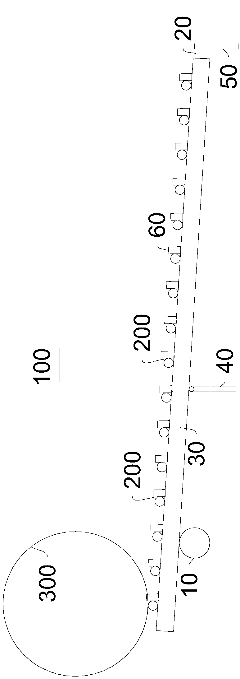
[0073] setting the carrier 30 obliquely relative to the horizontal plane;

[0074] Place the main ribs 200 on the fixed part 31 in sequence, so that multiple main ribs 200 are distributed side by side;

[0075] Place a plurality of reinforcement rings 300 on the main rib 200, so that the reinforcement ring 300 is placed correspondingly to the carrier 30, and the axial direction of the parallel reinforcement rings 300 is consistent with the axial direction of the main rib 200;

[0076] First, the main ribs 200 located on the carrier 30 close to the first fixing part 10 are welded to a plurality of reinforcement rings 300, so that the reinforcement rings 300 roll relative to the carrier 30, and the main ribs 200 on the carrier 30 are welded to multiple...


PUM


Abstract

The invention provides a welding auxiliary device and a welding method, and belongs to the technical field of reinforcement cage forming. The welding auxiliary device comprises a first fixing member,a second fixing member and a plurality of bearing parts. One end of each bearing part is connected with the first fixing member. The other end of each bearing part is connected with the second fixingmember. Each bearing part is provided with a plurality of fixing parts used for fixing main reinforcements. The fixing parts are distributed in the length direction of the corresponding bearing part at intervals. The multiple bearing parts are distributed in the length direction of the first fixing member at intervals. Through the welding auxiliary device, the main reinforcements needing to be welded can be prefixed, reinforcement rings are directly welded on the main reinforcements in a roll welding mode, the whole welding process is capable of saving time and effort and high in quality, andthe welding auxiliary device is low in cost and high in applicability. Through the welding method, reinforcement cages can be rapidly formed with high quality.

Description

technical field [0001] The invention relates to the technical field of steel cage forming, in particular to a welding auxiliary device and a welding method. Background technique [0002] Bored pile: refers to the pile hole formed in the foundation soil by means of mechanical drilling or manpower excavation at the project site, and a pile made by placing a steel cage and pouring concrete in it, so that the reinforced cage of the drilled pile The welding is fully in accordance with the design requirements. [0003] The welding of steel cage has the largest workload, the most cumbersome, and the longest time-consuming in the production of steel cages. It is an important link in the construction of bored piles. As an important process in the construction of bored piles, steel cage welding is an important process. Its welding quality and speed It often restricts the construction progress of on-site bored piles. [0004] The inventor found in the research that the traditional mo...

Claims


Application Information

Patent Timeline
Patent Type & Authority Applications(China)
IPC IPC(8): B23K11/06B23K11/36
CPCB23K11/06B23K11/36
Inventor 秦英斌朱永领
Owner HAIWEI ENG CONSTR CO LTD OF FIRSTHIGHWAY ENG CO LTD OF CCCC
Why Eureka
Try Eureka