Double-layer feeding and discharging mechanism with continuity

A coherent, double-layer technology, applied in manufacturing tools, metal processing equipment, metal processing, etc., can solve the problems of low production efficiency, high production cost, matching efficiency of feeding device automation equipment, etc., to improve production efficiency, Beat-saving, versatile effects

Pending Publication Date: 2018-05-29
INST OF INTELLIGENT MFG TECH JITRI
View PDF7 Cites 2 Cited by
  • Summary
  • Abstract
  • Description
  • Claims
  • Application Information

AI Technical Summary

Problems solved by technology

[0003] In order to solve the defects of low production efficiency, high production cost and the inability of the feeding device to match the efficiency of automation equipment in the prior art, the present invention provides a coherent double-layer loading and unloading mechanism

Method used


Image

  • Double-layer feeding and discharging mechanism with continuity
  • Double-layer feeding and discharging mechanism with continuity

Examples


Embodiment Construction

[0018] The specific embodiments of the present invention will be further described below in conjunction with the accompanying drawings. It should be noted here that the descriptions of these embodiments are used to help understand the present invention, but are not intended to limit the present invention.

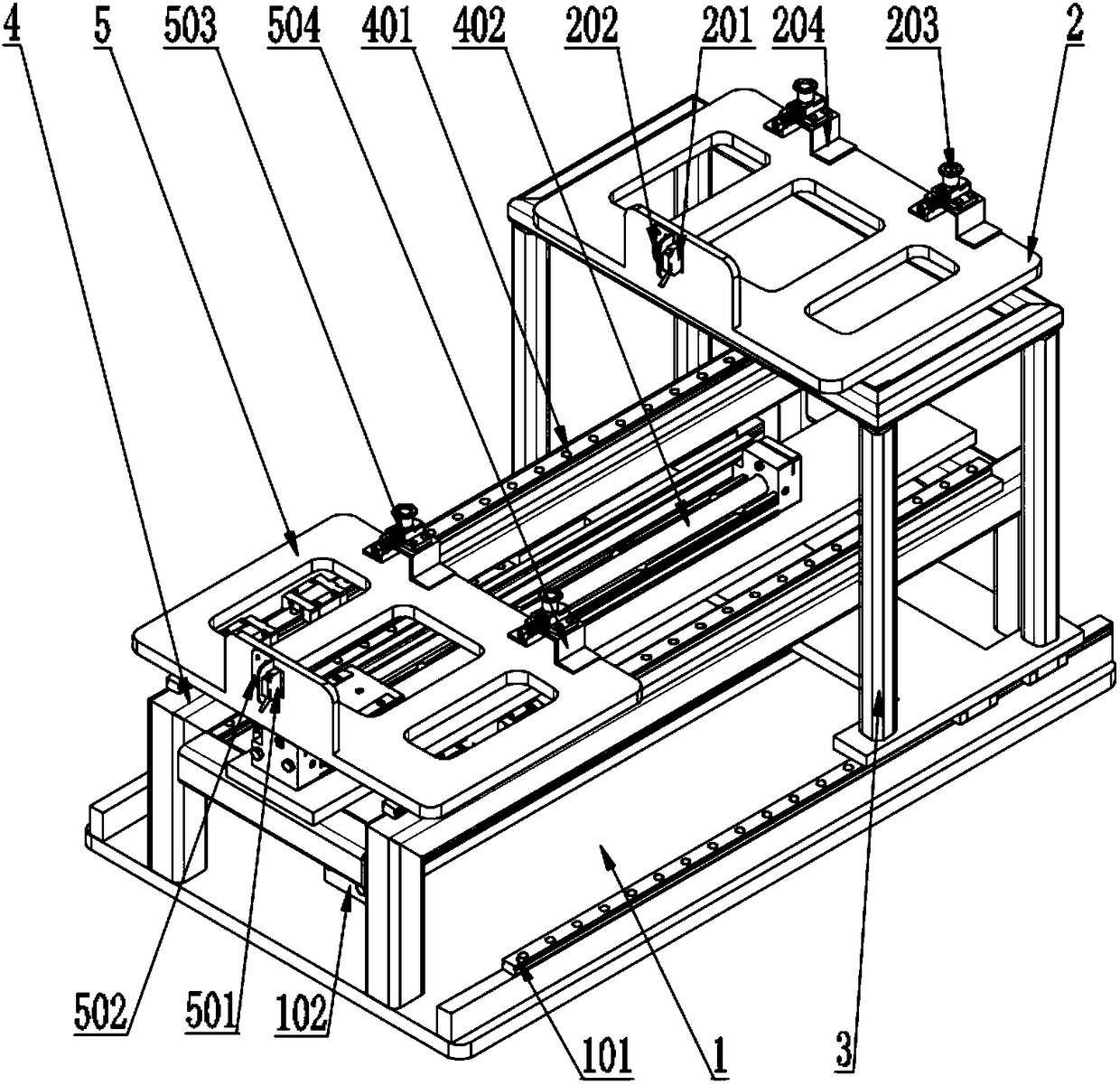
[0019] Such as figure 1 As shown, the continuous double-layer loading and unloading mechanism of the present invention mainly includes: a lower track layer 1 , an upper track layer 4 , an upper moving platform 2 and a lower moving platform 5 . The plane where the upper track layer 4 is located is above the plane where the lower track layer 1 is located. The two tracks of the lower track layer 1 are respectively located outside the two tracks of the upper track layer 4 . In order to facilitate the setting of the track and the movement of the platform on the track, the two tracks of the lower track layer 1 are parallel to the two tracks of the upper track layer 4 .

[0020...


PUM


Abstract

The invention discloses a double-layer feeding and discharging mechanism with continuity. The double-layer feeding and discharging mechanism with continuity comprises a lower rail layer, an upper raillayer, an upper moving platform and a lower moving platform. The plane where the upper rail layer is located is located above the plane where the lower rail layer is located, and two rails of the lower rail layer are located on the outer sides of two rails of the upper rail layer correspondingly. The upper moving platform is connected with the lower rail layer through a plurality of supporting rods. The lower moving platform is located on the plane where the upper rail layer is located, and is connected with the upper rail layer. A gap with the preset height is formed between the upper movingplatform and the lower moving platform. The double-layer feeding and discharging mechanism with continuity is low in manufacturing cost, high in efficiency, simple in structure, reliable to use and high in locating accuracy.

Description

technical field [0001] The invention belongs to the field of mechanical automatic processing, and in particular relates to a continuous double-layer loading and unloading mechanism. Background technique [0002] In machining, parts are generally assembled manually. In order to improve the efficiency of component assembly, there are also some fully automatic assembly machines in the prior art. However, most of the automatic assembly machines on the market feed individual parts separately, which greatly reduces the assembly efficiency. Moreover, most manufacturers still use pure manual loading and unloading mode, which has low production efficiency and high production cost, and cannot match the efficiency of automation equipment, resulting in waste of resources. Contents of the invention [0003] In order to solve the defects of low production efficiency, high production cost and the inability of the feeding device to match the efficiency of the automation equipment in the...

Claims


Application Information

Patent Timeline
Patent Type & Authority Applications(China)
IPC IPC(8): B23P19/00
CPCB23P19/001
Inventor 许爱芳甘胜平骆长俊慕金伯钱勇骆敏舟
Owner INST OF INTELLIGENT MFG TECH JITRI
Why Eureka
Try Eureka