Supercharge Your Innovation With Domain-Expert AI Agents!

Numerical control clamping device

A clamping device and guide rail technology, which is applied to metal processing machinery parts, maintenance and safety accessories, metal processing equipment, etc., can solve problems such as unfavorable workpiece clamping, and achieve the effect of saving materials and reducing costs

Inactive Publication Date: 2018-05-29
青岛炫昌能源装备有限公司
View PDF0 Cites 0 Cited by
  • Summary
  • Abstract
  • Description
  • Claims
  • Application Information

AI Technical Summary

Problems solved by technology

But the disadvantage is that the guide rail spans the entire workbench, which is not conducive to the clamping of the workpiece

Method used


Image

  • Numerical control clamping device
  • Numerical control clamping device

Examples


Embodiment Construction

[0016] The following will be further described in conjunction with the accompanying drawings, not to limit the scope of the present invention.

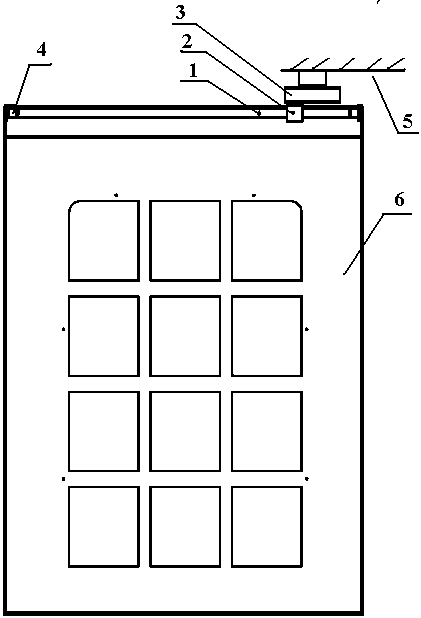
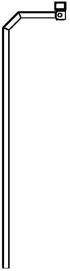
[0017] see figure 1 and figure 2 As shown, the present invention comprises guide rail 1, guide block 2, fixed seat 3, guide rail support 4 and frame 5, guide rail 1 is fixed on the protective door 6 by guide rail support 4, and guide block 2 is installed on frame 5 by fix seat 3 superior. During work, the guide rail 1 moves along with the protective door 6 . The guide rail 1 is aluminum alloy, and the guide rail 1 may also be alloy steel. The invention saves materials and reduces costs. The present invention shortens the length of the guide rail 1 . During work, the guide rail 1 is located on both sides of the workbench, which is more conducive to the clamping of workpieces (especially large workpieces).


PUM


Abstract

The invention relates to a numerical control clamping device which comprises a protective door and a rack. Guide rail supports are mounted on the two sides of the upper portion of the protective door,and a guide rail is fixed to the guide rail supports. A fixing seat is mounted on the rack, and a guiding block is arranged on the fixing seat. According to the numerical control clamping device, theguide rail mounted on the rack is usually divided into two sections which are fixed to two doors correspondingly, the guiding block is fixed to an outer protecting part, and in this way, work such asworkpiece clamping is facilitated.

Description

technical field [0001] The invention belongs to the technical field of mechanical manufacturing, and in particular relates to a numerical control clamping device. Background technique [0002] With the development of social economy, the application of CNC machining centers is becoming more and more extensive. In order to limit the movement direction of the protective door, a guiding device is required to set up a protective door in the CNC machining center. At present, most machining centers each The door is equipped with two guide blocks, and the guide rail is fixed on the frame, and the guide rail spans the entire working area. But the disadvantage is that the guide rail spans the entire workbench, which is not conducive to the clamping of the workpiece. Contents of the invention [0003] The present invention overcomes the deficiencies of the prior art and proposes a numerical control clamping device, which divides the guide rail usually installed on the frame into two...

Claims


Application Information

Patent Timeline
IPC IPC(8): B23Q11/08
CPCB23Q11/0891
Inventor 郝新光
Owner 青岛炫昌能源装备有限公司
Features
  • R&D
  • Intellectual Property
  • Life Sciences
  • Materials
  • Tech Scout
  • Unparalleled Data Quality
  • Higher Quality Content
  • 60% Fewer Hallucinations
Learn More