
Pneumatic tire with dual bead fillers

A technology of pneumatic tires and apex rubber, which is applied to tire parts, tire edges, transportation and packaging, etc., can solve the problem that the position of cord and apex is easy to separate, the boundary position of cord and wear-resistant rubber is separated, and the difference of stress and strain is large. and other problems to achieve the effect of reducing the risk of separation, without sacrificing the rigidity of the sidewall, and balancing the stress and strain

Inactive Publication Date: 2018-05-29
GITI RADIAL TIRE (ANHUI) CO LTD
View PDF17 Cites 3 Cited by
  • Summary
  • Abstract
  • Description
  • Claims
  • Application Information

AI Technical Summary

Problems solved by technology

[0004] 1. Due to the large difference between the tensile and compressive elastic modulus of the sidewall wear-resistant rubber and the cord, when the same magnitude of force is applied, the stress-strain difference between the two is large, resulting in the easy boundary between the cord and the wear-resistant rubber. produce separation;
[0005] 2. There is a large difference between the tension and compression elastic modulus of the cord and the first apex and the cord. When the force of the same magnitude is applied, the stress and strain difference between the two is relatively large, which leads to the separation of the cord and the apex easily;

Method used


Image

  • Pneumatic tire with dual bead fillers
  • Pneumatic tire with dual bead fillers
  • Pneumatic tire with dual bead fillers

Examples


Embodiment 1

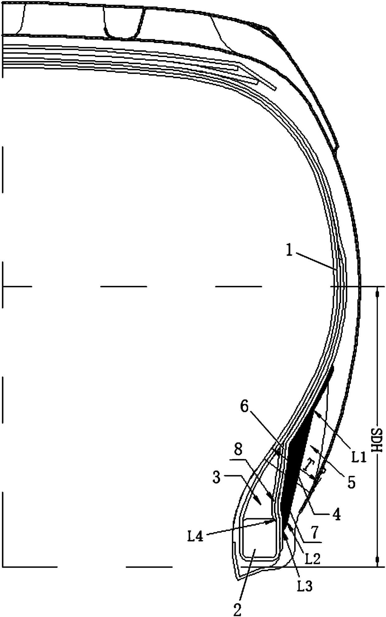
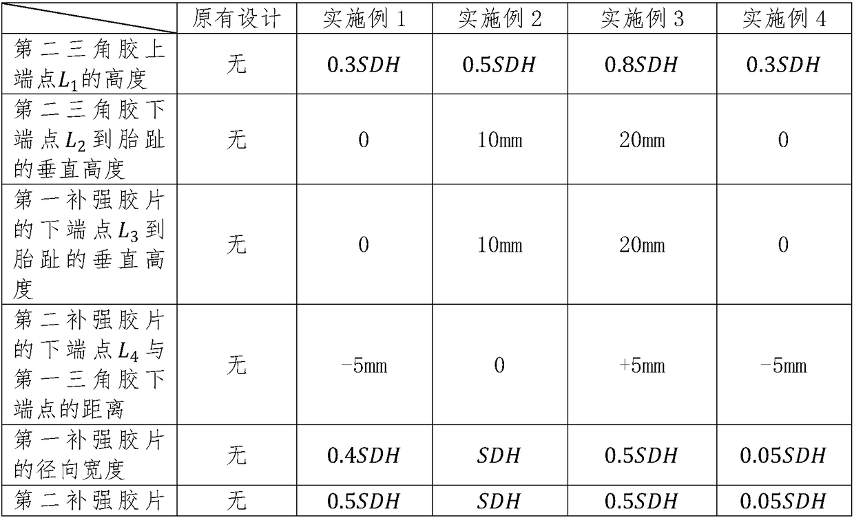
[0030] End point L on the second apex 1 The height is 0.3SDH, the lower endpoint of the second apex L 2 Located at the fetal toe, where SDH is the vertical height from the widest point of the sidewall to the fetal toe.

[0031] The lower end point L of the first reinforcing film 3 Also located at the fetal toe, the lower end point L of the second reinforcing film 4 Located 5mm below the lower end of the first apex.

[0032] The radial width of the first reinforcing film is 0.4SDH, the radial width of the second reinforcing film is 0.5SDH, and the thickness is 0.2T, where SDH is the vertical height from the widest part of the sidewall to the tire toe, and T is the rim line total thickness.

Embodiment 2

[0034] End point L on the second apex 1 The height is 0.5SDH, the lower endpoint of the second apex L 2 The vertical height to the fetal toe is 10mm, where SDH is the vertical height from the widest point of the sidewall to the fetal toe.

[0035] The lower end point L of the first reinforcing film 3 The vertical height to the fetal toe is 10mm, the lower end point L of the second reinforcing film 4 Located at the lower end of the first apex.

[0036] Both the radial width of the first reinforcing film and the second reinforcing film are SDH, and the thickness is 0.5T, wherein SDH is the vertical height from the widest part of the sidewall to the tire toe, and T is the total thickness at the rim line.

Embodiment 3

[0038] End point L on the second apex 1 The height is 0.8SDH, the lower endpoint of the second apex is L 2 The vertical height to the fetal toe is 20mm, where SDH is the vertical height from the widest point of the sidewall to the fetal toe.

[0039] The lower end point L of the first reinforcing film 3 The vertical height to the fetal toe is 20mm, the lower end point L of the second reinforcing film 4 Located 5mm above the lower end of the first apex.

[0040] The radial width of the first reinforcing film is 0.5SDH, the radial width of the second reinforcing film is 0.5SDH, and the thickness is 0.2T, where SDH is the vertical height from the widest part of the sidewall to the tire toe, and T is the rim line total thickness.


PUM

PropertyMeasurementUnit
Vertical heightaaaaaaaaaa

Abstract

The invention provides a pneumatic tire with dual bead fillers. The pneumatic tire comprises a tire body, a tire bead, a first bead filler and a tire side wear-resisting adhesive, the tire body surrounds the tire bead and the first bead filler and achieves anti-package from the inner side in the axial direction of the tire to the axial direction of the tire, the first bead filler and the tire sidewear-resisting adhesive extend upwards in the radial direction of the tire from the tire bead, a second bead filler is arranged between one side of the anti-package part of the tire body and the tireside wear-resisting adhesive, the height L1 of the upper end of the second bead filler is equal to (0.3-0.8)SDH, and the perpendicular distance between the bead toe and the lower end of the second bead filler is 0-20 mm, wherein the SDH is the perpendicular distance between the widest position of the tire side wall and the bead toe. The second bead filler and a reinforcing film are additionally arranged as a buffer region, the stress-strain difference between different components is decreased, and therefore the separation risk among various materials is lowered.

Description

technical field [0001] The invention relates to the technical field of tires, in particular to a pneumatic tire with double apexes. Background technique [0002] For tires made of rubber, fiber, and metal skeleton materials, deformation will occur as long as a certain air pressure is injected. While the tire is running, due to the applied load, driving force, braking force and lateral force, etc., a certain part of the tire will be stressed. Through the analysis of finite element tools, it can be found that the tire at the spout The stress and strain are relatively large. Due to the different tensile and compressive moduli of elasticity between different materials, different materials are prone to separation, which is not conducive to durability. Generally, separation is most likely to occur between the cord and the sidewall wear-resistant rubber, and between the cord and the apex. In the actual use process, it is manifested as bead bulging and bursting of the tire, which ...

Claims


Application Information

Patent Timeline
IPC IPC(8): B60C15/06B60C15/04
Inventor 潘世瑞余本祎蔡莹莹李翠
Owner GITI RADIAL TIRE (ANHUI) CO LTD
Learn More