High-altitude anti-inclination steel frame structure and installation method thereof

An installation method and steel frame technology, applied in the direction of building structure, construction, etc., can solve the problems of lack of stability and wind resistance, poor resistance to external force, poor resistance to external force, etc., to achieve enhanced stability and wind resistance , Strong wind and earthquake resistance, and the effect of improving the ability to resist external forces

Pending Publication Date: 2018-05-29
JIANGSU HUNING STEEL MECHANISM
View PDF6 Cites 1 Cited by
  • Summary
  • Abstract
  • Description
  • Claims
  • Application Information

AI Technical Summary

Problems solved by technology

[0005] 1. Most of the current high-altitude steel frame structures do not have excellent stability and wind resistance, poor resistance to external forces, prone to structural looseness, and safety accidents
[0006] 2. Most of the current high-altitude steel frame structures adopt fully welded and integrally formed structures, which have high structural strength, poor toughness, and poor resistance to external forces

Method used


Image

  • High-altitude anti-inclination steel frame structure and installation method thereof
  • High-altitude anti-inclination steel frame structure and installation method thereof
  • High-altitude anti-inclination steel frame structure and installation method thereof

Examples


Embodiment 1

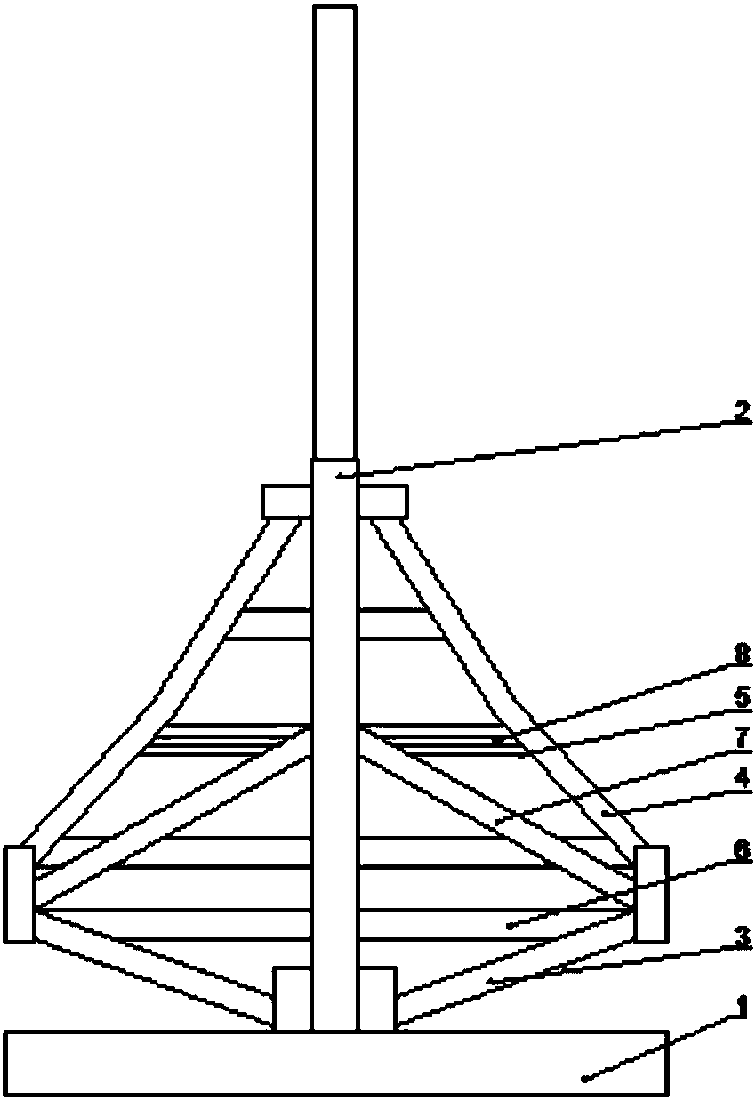
[0038] Such as figure 1 A high-altitude anti-tilt steel frame structure shown includes: a supporting beam 1, a mast 2, a supporting rod 3, a supporting oblique rod 4 and a hoop rod 5, the supporting beam 1 is provided with a mast 2, and the mast 2 The lower end is connected with a supporting rod 3, the middle section of the mast 2 is provided with a supporting diagonal rod 4, and the supporting diagonal rod 4 is provided with a circumferential rod 5; one end of the supporting rod 3 is connected to one end of the supporting diagonal rod 4 The ends are connected.

[0039] The mast 2 described in this embodiment includes an upper mast and a lower mast, and the upper mast and the lower mast are connected and fixed by bolts and nuts, and the supporting rod 3 and the supporting slanting rod 4 are both arranged on the lower mast.

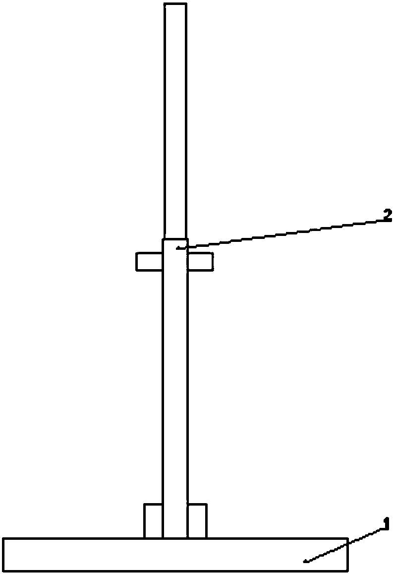
[0040] The support beam 1 described in this embodiment is welded with a limit clamp, and a mast 2 is arranged inside the limit clamp, and the limit clamp...

Embodiment 2

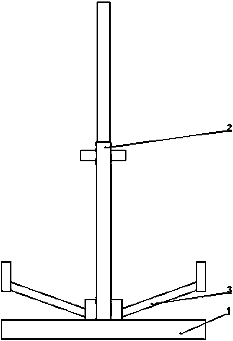
[0048] Such as Figure 2-6 A high-altitude anti-tilt steel frame structure shown includes: a supporting beam 1, a mast 2, a supporting rod 3, a supporting oblique rod 4 and a hoop rod 5, the supporting beam 1 is provided with a mast 2, and the mast 2 The lower end is connected with a supporting rod 3, the middle section of the mast 2 is provided with a supporting diagonal rod 4, and the supporting diagonal rod 4 is provided with a circumferential rod 5; one end of the supporting rod 3 is connected to one end of the supporting diagonal rod 4 The ends are connected.

[0049] The installation method of a high-altitude anti-tilt steel frame structure described in this embodiment includes construction from the inside to the outside and from the bottom to the top, and specifically includes the following steps: Step 1: Install the support beam 1, and use the crawler crane to lift the support Beam 1 is fixed by welding; step 2: install mast 2, hoist mast 2 with a crawler crane, snap ...


PUM


Abstract

The invention discloses a high-altitude anti-inclination steel frame structure. The high-altitude anti-inclination steel frame structure comprises a supporting beam, a mast, supporting rods, inclinedsupporting rods and an annular rod. The mast is arranged on the supporting beam, the supporting rods are connected to the lower end of the mast, the inclined supporting rods are arranged in the middlesection of the mast, and the annular rod is arranged on the inclined supporting rods. The tip of one end of each supporting rod is connected with the tip of one end of the corresponding inclined supporting rod. The invention further discloses an installation method of the high-altitude anti-inclination steel frame structure. By the adoption of the full-steel structure, the intensity of the top ofa tower is enhanced; by the adoption of bolt connection, welding, buckling connection and other connection modes, the tenacity of the top of the tower is improved.

Description

technical field [0001] The invention belongs to the field of construction engineering, and in particular relates to a high-altitude anti-tilt steel frame structure and an installation method thereof. Background technique [0002] Jingda Baoen Temple is the oldest Buddhist temple in Chinese history, the largest and highest-standard temple, and the first among hundreds of temples. The glazed pagoda of Dabaoen Temple has always been the tallest building in China and a world architectural wonder, but unfortunately it was destroyed in the war. Therefore, this application has made a series of studies on how to rebuild the glazed pagoda of Dabaoen Temple. [0003] The new protection tower of the underground palace of Dabaoen Temple has nine floors above the ground. According to the shape of the ancient pagoda, starting from the third floor, the height of each floor decreases from bottom to top. The height of the first floor is 12.1 meters; the height of the second floor is 3.9 m...

Claims


Application Information

Patent Timeline
Patent Type & Authority Applications(China)
IPC IPC(8): E04B1/24E04B1/38
CPCE04B1/24E04B1/38
Inventor 蒋良军杨国松李建华付鹏方佑民李爱华
Owner JIANGSU HUNING STEEL MECHANISM
Why Eureka
Try Eureka