
Integrated pressure reducing valve

A pressure reducing valve and valve body technology, applied in the direction of valve details, safety valves, balance valves, etc., can solve the problems of large size, long response time, high safety requirements, etc., achieve stable outlet pressure, improve pressure regulation, and compact structure effect

Active Publication Date: 2018-05-29
上海瀚氢动力科技有限公司
View PDF6 Cites 4 Cited by
  • Summary
  • Abstract
  • Description
  • Claims
  • Application Information

AI Technical Summary

Problems solved by technology

[0003] Different from traditional energy vehicles or pure lithium battery charging vehicles, the gas supply system of hydrogen fuel cell electric vehicles is connected with a certain pressure of hydrogen gas source and fuel cell stack system, which has a relatively complex structure and high safety requirements. Technical characteristics, so the gas supply system of the prior art adopts multiple parts and separate parts, its structure is relatively complex, the external size is large, and the response time of adjustment is long, and the reliability is low

Method used


Image

  • Integrated pressure reducing valve
  • Integrated pressure reducing valve
  • Integrated pressure reducing valve

Examples


Embodiment Construction

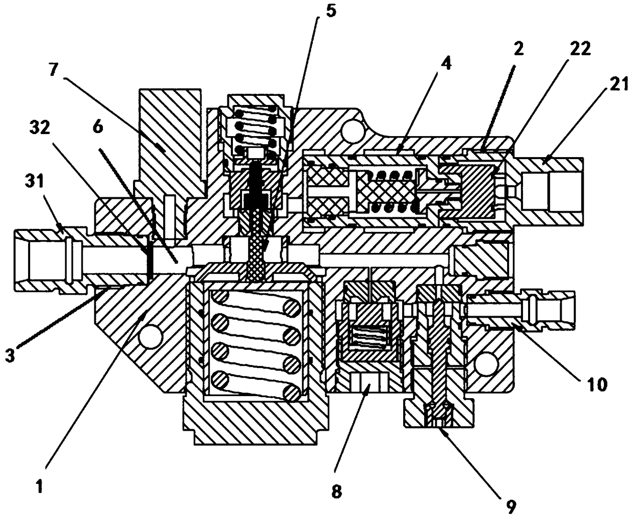
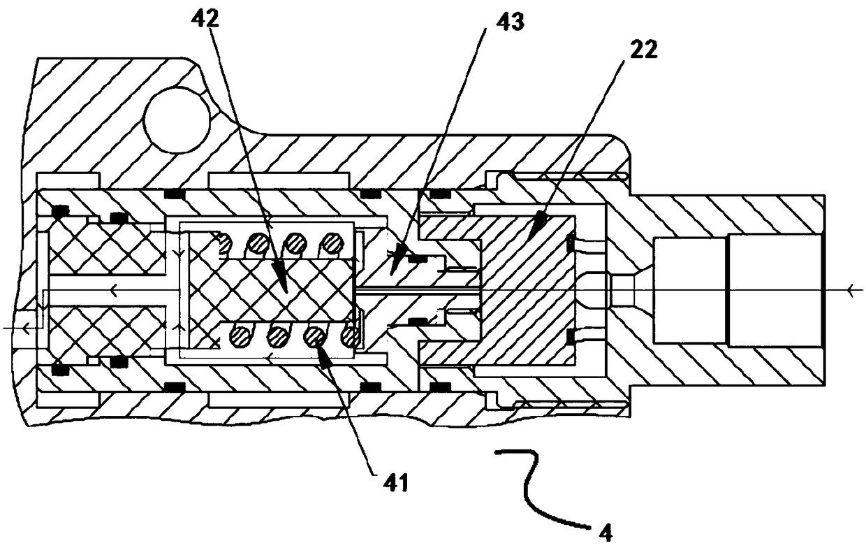
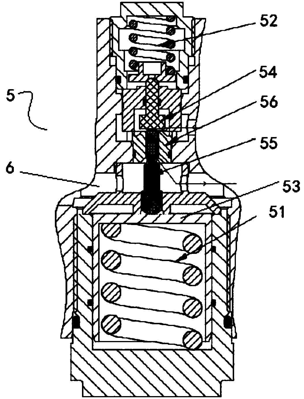
[0023] Such as Figures 1 to 3 As shown, the present invention provides an integrated pressure reducing valve, which includes: a valve body 1, an inlet 2 and an outlet 3 located outside the valve body 1, and a pressure reducing system located inside the valve body 1, wherein: the The inlet 2 is in fluid communication with the gas source outlet of the hydrogen fuel cell electric vehicle, and the outlet 3 is in fluid communication with the downstream stack of the hydrogen fuel cell electric vehicle; and the decompression system includes: located at the inlet 2 and the The first-stage pressure-relief valve 4 and the second-stage pressure-relief valve 5 connected between the outlets 3 and in fluid order, and the first-stage axis of the first-stage pressure-relief valve 4 and the second-stage pressure-relief valve The second level axes of 5 are arranged perpendicular to each other.

[0024] The decompression valve in the present invention has a two-stage decompression system to en...


PUM


Abstract

The invention discloses an integrated pressure reducing valve. The integrated pressure reducing valve comprises a valve body, an inlet and an outlet located outside the valve body, and a pressure reducing system located inside the valve body, wherein the inlet is in fluid communication with a gas source outlet of a hydrogen fuel cell electric vehicle, and the outlet is in fluid communication witha downstream electric reactor of the hydrogen fuel cell electric vehicle; and a pressure reducing system comprises a first-stage pressure reducing valve and a second-stage pressure reducing valve which are located between the inlet and the outlet and are in fluid sequence communication, and the first-stage axis of the first-stage pressure reducing valve and the second-stage axis of the second-stage pressure reducing valve are vertically arranged. According to the integrated pressure reducing valve, the two-stage pressure reducing system is arranged, so that the stability of outlet pressure isguaranteed, meanwhile, the two stages of the pressure reducing valves are vertically arranged, so that the size of main body structure is optimized while the pressure adjustment is further improved, and more compact structure is formed.

Description

technical field [0001] The invention relates to an integrated pressure reducing valve, in particular to an integrated pressure reducing valve used in a hydrogen supply system of a fuel cell. Background technique [0002] With the growing automobile industry, there are more and more types of vehicles, among which the development of electric vehicles is particularly rapid. As a relatively core technical field in the field of electric vehicles, electric vehicles using hydrogen as fuel cells have gradually become a major direction of technology development and market expansion. [0003] Different from traditional energy vehicles or pure lithium battery charging vehicles, the gas supply system of hydrogen fuel cell electric vehicles is connected with a certain pressure of hydrogen gas source and fuel cell stack system, which has a relatively complex structure and high safety requirements. Technical characteristics, so the air supply system of the prior art adopts multiple parts ...

Claims


Application Information

Patent Timeline
IPC IPC(8): F16K17/20F16K31/122F16K51/00B01D35/02
CPCB01D35/02F16K17/20F16K31/1221F16K51/00
Inventor 张向前
Owner 上海瀚氢动力科技有限公司
Learn More