Screening device used after coal mining

A screening device and technology for coal mines, applied in the field of coal mine machinery, can solve the problems of undetected coal mine omissions, high coal mines unable to pass, inaccurate counting, etc., achieving high screening efficiency, avoiding omission statistics, and ensuring accuracy Effect

Active Publication Date: 2018-06-01
广东五月花网络科技有限公司
6 Cites 0 Cited by

AI-Extracted Technical Summary

Problems solved by technology

[0003] However, the existing screening devices used for coal mine mining still have certain defects in use. Because the volume of the coal mines is generally uneven, there are large and small, so when the number of c...

Method used

As a kind of technical optimization scheme of the present invention, import frame 1, outlet frame 2 all are flexibly connected between the spring 14 on the telescoping rod 12 of its bottom and support pad 8, the connection of import frame 1 and outlet frame 2 The height adjustment is more flexible.
When the present invention is in use, the import frame 1 and the outlet frame 5 of the device are respectively installed on the conveyor belt initial end and the end of the transmission coal mine, and the device is controlled by the control cabinet 4 of the PZ-30 through the operation of the device. The left slot 7 and the right slot 10 are arranged on the side walls of both sides of the exit frame 2, and three groups of photoelectric sensors 15 of model LR-W are respectively placed in the left slot 7 and the right slot 10. , and the three groups of photoelectric sensors 15 on the left chute 7 and the right chute 10 are placed on different levels one by one, so that the device can not only monitor and detect the number of coal mines passing throug...

Abstract

The invention discloses a screening device used after coal mining. The screening device comprises an inlet support, an outlet support, a conveying belt, a control cabinet, an alarm lamp, a motor, a left groove, a supporting mat, a distance inductor, a right groove, a strut, a stretchable rod, a connecting rod, a spring and photoelectric inductors. The screening device has the beneficial effects that the left groove and the right groove are formed in the side walls of the two sides of the inlet support and the outlet support, three sets of photoelectric inductors arranged at the upper portions,the middle portions and the lower portions are arranged inside the left groove and the right groove correspondingly, the three sets of photoelectric inductors on the left groove and the right grooveare correspondingly placed at different horizontal heights one by one, and therefore when the device is used, the number of coal mine passing through the screening device can be monitored and detected, the height and size of each coal mine can be judged, the condition that the coal mine with the small size and at the low height is not counted can be avoided, the inlet support and the outlet support run at the same time, the transferred coal mine is subject to comparison and detection two times, and the data accuracy is guaranteed.

Application Domain

Sorting

Technology Topic

Coal miningInductor +2

Image

  • Screening device used after coal mining
  • Screening device used after coal mining
  • Screening device used after coal mining

Examples

  • Experimental program(1)

Example Embodiment

[0017] The technical solutions in the embodiments of the present invention will be clearly and completely described below with reference to the accompanying drawings in the embodiments of the present invention. Obviously, the described embodiments are only a part of the embodiments of the present invention, but not all of the embodiments. Based on the embodiments of the present invention, all other embodiments obtained by those of ordinary skill in the art without creative efforts shall fall within the protection scope of the present invention.
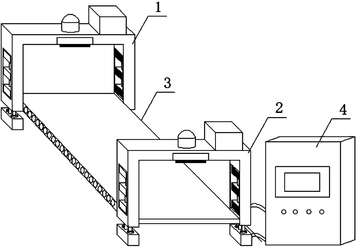
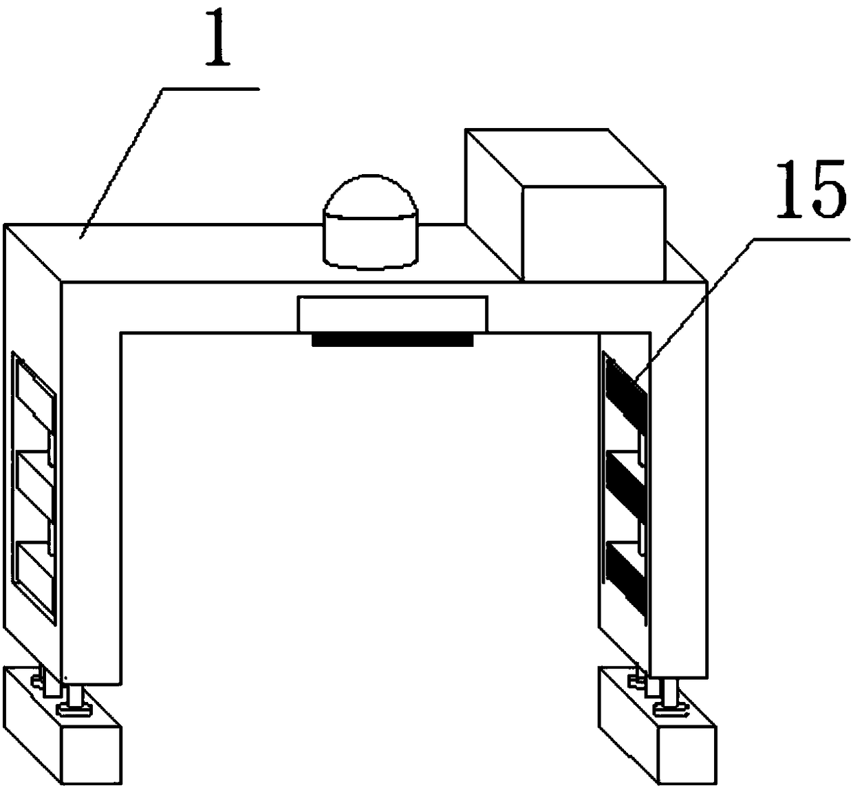
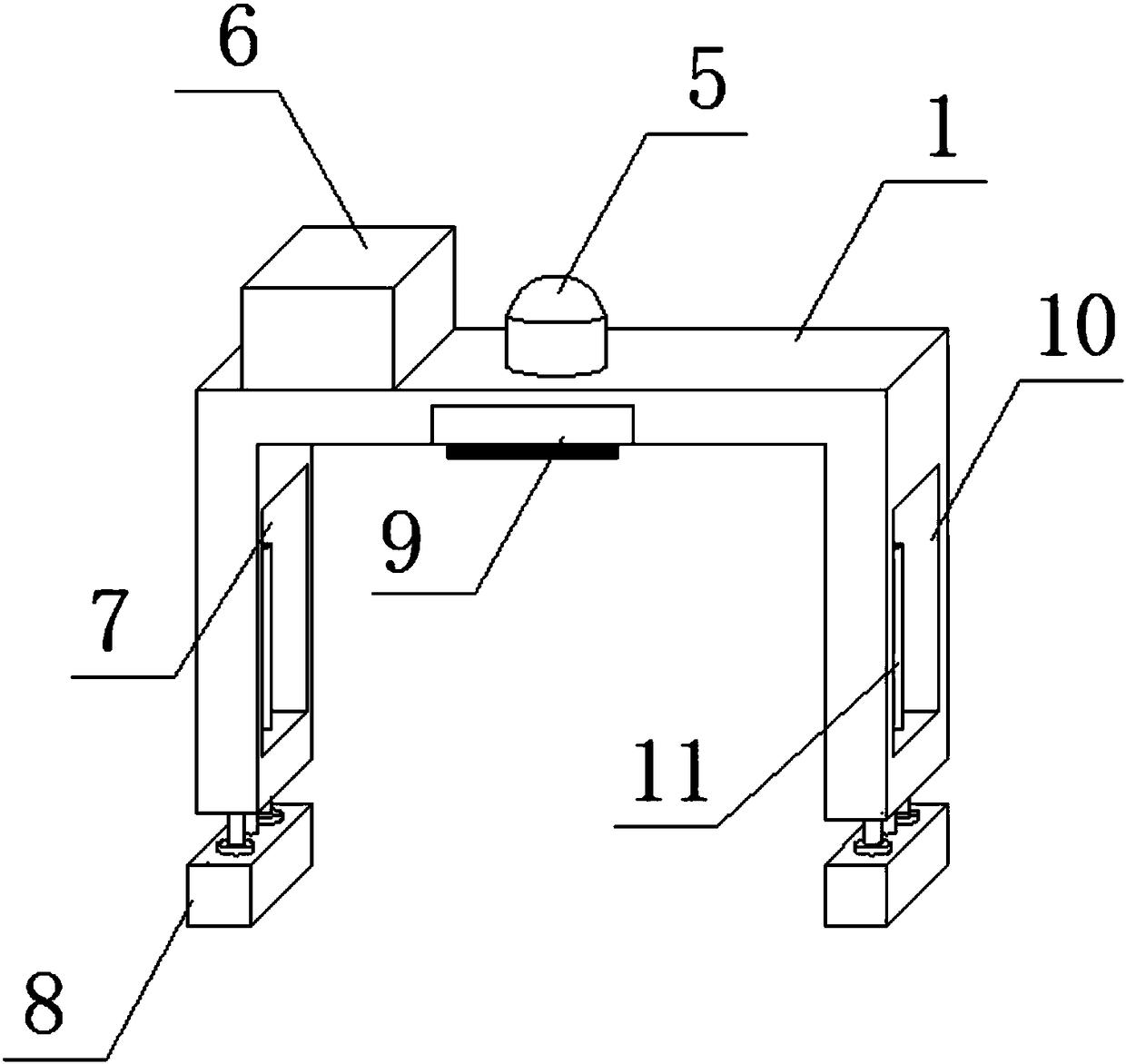
[0018] see Figure 1-4 As shown, a screening device for coal mining, including an inlet frame 1, a control cabinet 4 and an outlet frame 2, a conveyor belt 3 is installed at the bottom of the inlet frame 1, an outlet frame 2 is installed at the end of the conveyor belt 3, and one side of the outlet frame 2 is placed Control cabinet 4, alarm lights 5 are installed on the top of inlet frame 1 and outlet frame 2, motor 6 is installed on one side of alarm light 5, and distance sensors 9 are installed on both sides of the top of inlet frame 1 and outlet frame 2. A hollow left slot 7 is provided on the side wall of the same side as the outlet rack 2, and a hollow right slot 10 is provided on the other side wall of the inlet rack 1 and the outlet rack 2. The left slot 7 and the right slot 10 are installed with three A photoelectric sensor 15 is installed, and support rods 11 are installed inside the left slot 7 and the right slot 10. Two support pads 8 are installed at the bottom of the inlet frame 1 and the outlet frame 2, and two telescopic rods 12 are installed above the support pads 8. The telescopic rods A spring 14 is installed in the middle of 12 , a post 13 is installed between the two telescopic rods 12 , and the top of the post 13 is connected with the support rod 11 .
[0019] As a technical optimization scheme of the present invention, the photoelectric sensors 15 installed in the left slot 7 and the right slot 10 are divided into three groups: upper, middle and lower, and each two groups of photoelectric sensors 15 are correspondingly placed at the same level In terms of height, three groups of photoelectric sensors 15 can fully detect coal mines with different heights and sizes.
[0020] As a technical optimization scheme of the present invention, the support rod 11 is movably connected with the motor 6 through the transmission rod running through the inlet frame 1 and the outlet frame 2, and the three groups of photoelectric sensors 15 can rise and fall on the support pad 8 remains at its original height.
[0021] As a technical optimization solution of the present invention, the support rod 11 penetrates the three groups of photoelectric sensors 15 inside the left slot 7 and the right slot 10 , and the three groups of photoelectric sensors 15 can be stabilized inside the left slot 7 and the right slot 10 .
[0022] As a technical optimization scheme of the present invention, the inlet frame 1 and the outlet frame 2 are movably connected with the support pad 8 through the spring 14 on the telescopic rod 12 at the bottom thereof, and the height adjustment of the inlet frame 1 and the outlet frame 2 is relatively flexible.
[0023] As a technical optimization scheme of the present invention, the inlet rack 1 and the outlet rack 2 are electrically connected to the control cabinet 4 through wires, and each component inside the device has sufficient power sources during operation.
[0024] When the present invention is in use, the inlet frame 1 and the outlet frame 5 of the device are respectively installed at the initial end and the end of the conveyor belt for conveying coal mines. 2. A left slot 7 and a right slot 10 are arranged on the side walls on both sides. Inside the left slot 7 and the right slot 10, three groups of photoelectric sensors 15, which are divided into upper, middle, and lower models, are LR-W. The slots 7 and the three groups of photoelectric sensors 15 on the right slot 10 are placed at different levels one by one, so that the device can not only monitor and detect the number of coal mines passing through, but also monitor the number of coal mines passing through. The height and volume are judged, and it can prevent coal mines with smaller volumes and lower heights from not being counted. Both the inlet rack 1 and the outlet rack 2 work together to compare and detect the transmitted coal mines twice, so as to ensure the accuracy of the data. . By installing the distance sensor 9 of the model APM-12D23-20-DF8 on both side walls of the top of the inlet rack 1 and the outlet rack 2, when the height of the passing coal mine is greater than the maximum height of the inlet rack 1, the distance sensor 9 It is detected in advance that the control cabinet 4 controls the operation of the support pads 8 at the bottom of the inlet rack 1 and the outlet rack 2, and the telescopic rod 12 above the support pad 8 releases the spring 14, thereby raising the height of the inlet rack 1 and the outlet rack 2, thereby avoiding Coal mines with large heights cannot pass the unit, even if the unit is damaged while being transported on the conveyor 3.
[0025] It will be apparent to those skilled in the art that the present invention is not limited to the details of the above-described exemplary embodiments, but that the present invention may be embodied in other specific forms without departing from the spirit or essential characteristics of the invention. Therefore, the embodiments are to be regarded in all respects as illustrative and not restrictive, and the scope of the invention is to be defined by the appended claims rather than the foregoing description, which are therefore intended to fall within the scope of the claims. All changes within the meaning and scope of the equivalents of , are included in the present invention. Any reference signs in the claims shall not be construed as limiting the involved claim.
[0026] In addition, it should be understood that although this specification is described in terms of embodiments, not each embodiment only includes an independent technical solution, and this description in the specification is only for the sake of clarity, and those skilled in the art should take the specification as a whole , the technical solutions in each embodiment can also be appropriately combined to form other implementations that can be understood by those skilled in the art.

PUM

no PUM

Description & Claims & Application Information

We can also present the details of the Description, Claims and Application information to help users get a comprehensive understanding of the technical details of the patent, such as background art, summary of invention, brief description of drawings, description of embodiments, and other original content. On the other hand, users can also determine the specific scope of protection of the technology through the list of claims; as well as understand the changes in the life cycle of the technology with the presentation of the patent timeline. Login to view more.

Similar technology patents

Knowledge base supported spatial database design method

InactiveCN101477549AGuaranteed accuracyAchieve an optimized design
Owner:CHINESE ACAD OF SURVEYING & MAPPING

Train tracking method based on information redundancy

ActiveCN104149822AGuaranteed accuracyKeep Tracking
Owner:NARI TECH CO LTD

Classification and recommendation of technical efficacy words

Why Eureka
Try Eureka